¶ Root 4 Lite Assembly Guide for Newbies
Please note: This Assembly guide was community made by #RobF - please send your love his way!
If you would like to support the project in any shape or form, please get in touch with Pete!
¶ Introduction
So, you’ve watched all Pete’s YouTube videos, admired the elegant simplicity of the Root 4 Lite (R4L) design. You’ve compared the costs of buying a Chinese 3018 engraver or other DIY CNCs and can see a strength, performance, simplicity benefit in the Root CNCs. You’ve got access to a 3D printer and may have even started printing Root CNC parts. The only problem is you’ve never built a CNC or operated one before. Fear not, others have been this way and succeeded with some planning and patience.
This guide aims to provide a bit more detail on how to plan, print, build, and check basic operation of our R4L CNC.
¶ Resources
Root 4 Lite Github: Link Here
¶ Useful Links
- Bill of Materials (BOM): Link here
- Source STL and DXF Files: Link here
- Working Area spreadsheet calculator: Working%20Area.xlsx
¶ Useful Videos
YouTube – make sure you’re familiar with the 4 R4L assembly videos:
- Another 3D Printed CNC Machine? PT1
- Building a small High performance 3D printed CNC machine – Root 4 Lite PT2
- 3D Printed CNC Machine – Root 4 Lite PT3
- Root 4 Lite PT4 – the final stage assembly for the DIY 3D printed CNC machine
¶ Social links
- Root 4 Lite CNC Webpage
- Facebook Group
- Discourse
- Root CNC Discord Channel Great for quick answer to questions
- Thingiverse
- Youtube
¶ Planning and Preparation
¶ Practicalities
Where is your machine going to live, and can your significant other or neighbours cope with the noise and dust? How much space do you realistically have available. What materials do you expect to be cutting? The Root 4 Lite is a great compromise between relatively easy to understand parts, few special tools, strong design, and flexible sizing options.
The majority of 3D parts are not overly complex, show thoughtful design to avoid weak points, and will fit on the baseplate of a modest 3D printer (200x200mm).
¶ 3D printed parts
These need to be dimensionally precise – check your printer is calibrated and capable of reproducing parts to correct sizing. Consider printing a 20mm calibration cube. Aim to print with more walls than usual (e.g. 3-6), higher % infill. Layer sizes of 0.3 – 0.4 mm printed in PLA, PLA+, or ABS should all be fine. Where supports are required be prepared to remove as much of this as possible later. Most parts contain cavities or indentations for receiving bolts and nuts – check these spots are particularly clean before assembly begins.
¶ Sizing
Use the excellent sizing spreadsheet from the Github site. Bigger is not always better – for ballscrew sizes approaching 750-1000mm, consider building a full Root 4 CNC for a stronger, more capable (and more expensive) machine. The spreadsheet assumes you will be using 12mm thick side panels. Warning: If you use thicker or thinner material, the size of your X axis ballscrews and Box Section Lengths may need adjustment.
The R4L side panels contain main important mounting holes for the Y axis carriages and X axis assemblies. It is highly recommended you consider purchasing these from the Root CNC website shop, or have them made up locally (from the BOM DXF files section). If possible avoid attempting to cut them manually – it will make your building significantly easier.
The Github site also includes a DXF file for preparing a suitable 18mm baseboard with holes positions for mounting Y Axis supports and threaded inserts.
¶ Choice of Spindle/Router
Pete has designed the R4L specifically for a cooled 240V spindle driven by a VFD. This should result in optimal control over spindle speed, cutting power, noise and longevity. It is also possible to fit a 240V/110V router (e.g. Makita RTO700C).
For more information on spindles, please check out the Bill of Materials (BOM) Link Here
¶ Choice of Control Hardware/Firmware
Any solution that will drive at least 4 axes is theoretically suitable. A robust and future-proof solution would be Pete’s own “Root Controller”, offering full opto-isolation and a multitude of driver and control options, Wifi operation and other benefits of ESP32 GRBL FluidNC. Beginners or those on a budget might consider an Arduino Uno or Mega solution with suitable shield (e.g. RAMPS).
¶ Choice of Box Section Rails
Aluminum box section is strong and light and won’t corrode. Steel box section may need a little more cleaning, and if possible check the sizing with calipers before purchase. Steel sections may be helpful for section lengths above 750mm. Aluminum is fine otherwise.
¶ Hardware
If you’re not going to buy all the required parts straight away, consider at least ordering these parts first to allow assembly of the Y rails and X assembly:
- M5x60 pan head bolts (for the 8 carriages and 625 bearings)
- M5 loc nuts
- M5 washers
- M3x14mm cap head bolts
- M3 nuts
- M3 standard and penny washer
- Side panels
- Baseboard
- Box sections (aluminum or steel)
- Consider buying a set of bolts, washers and screws off Aliexpress or eBay initially
-E.g. “1080pcs M2/M3/M4/M5 stainless steel bolts nuts screws heax head assorted”- (then buy specific items as needed afterwards)
¶ Tools
A set of extra-long Allen Keys with “ball ends” is recommended for R4L assembly. Although not essential, these make some assembly steps (e.g. mounting steppers to motor mounts) much easier.
¶ Assembly
General Notes: The assembly guide below is a suggestion on how to proceed. Steps may not necessarily have to be executed in the order shown, but others have found this a safe way to put the R4L together.
¶ Baseboard Preparation
MDF or marine plywood are both suitable material. It’s not essential to seal and paint the CNC sideboards or baseplate, but it may help avoid long term swelling from moisture, particularly if you will be using MDF.
MDF is particularly prone to absorption of both sealers and paint. Consider applying at least 2 sealing coats before painting.
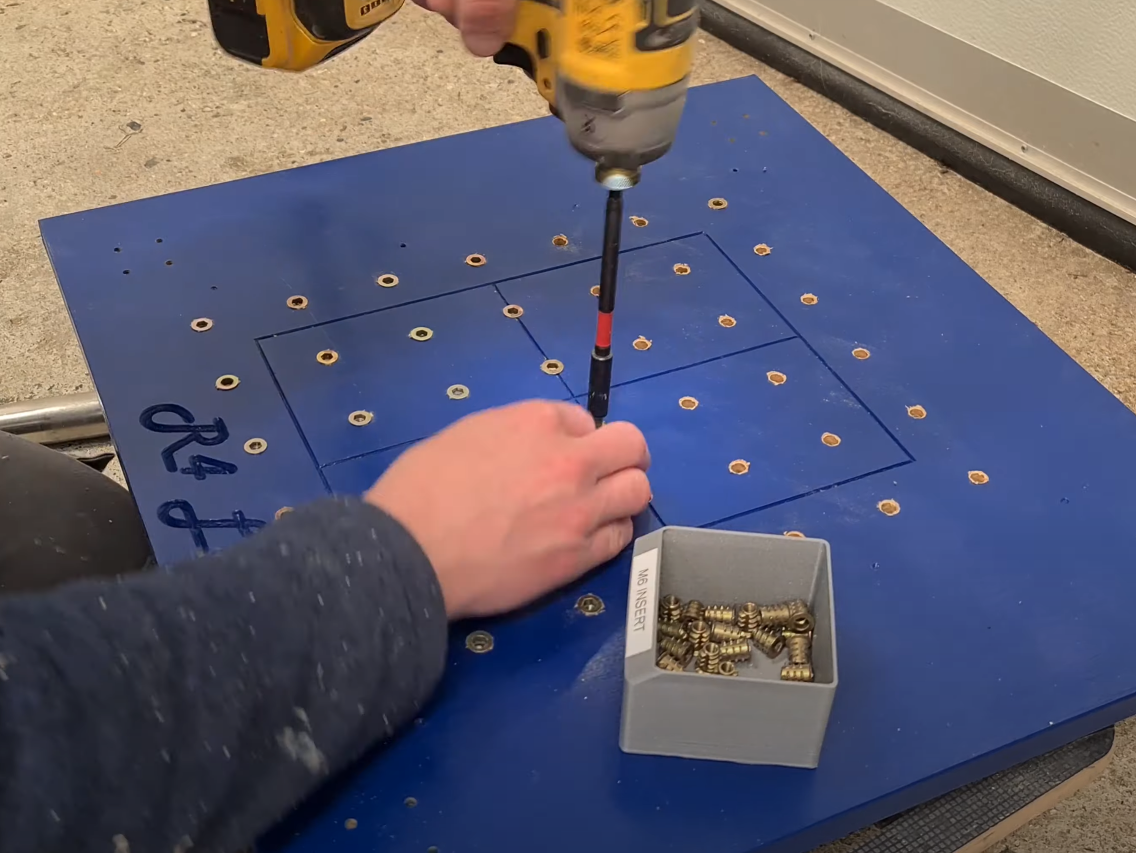
It is easier to decide on any mounting hardware options before assembly, along with drilling holes and mounting inserts.
If you want to build a different size machine, there is a handly calculator to work out the size of the machine vs build area vs length of box sections: LINK Working Area Spreadsheet
There is also a handy tool to generate the a matrix of mounting holes within the baseboard, to aid in the mounting of work peices. This tool can be brought and downloaded from the store Drill Location spreadsheet tool
¶ Baseboard Video reference
- R3L detailed build - 10:55 onwards
- R4L Part one 7:49 onwards)
¶ Carriages
Ensure any leftover support plastic inside the printed carriages is cleaned away. A small allen key just large enough to clear the slot cut outs can help. You may have more or less cleaning to do depending on how precise your 3D printer is creating the many internal cavities. Gently run an M3 drill bit through the side holes to ensure the full depth is clear.
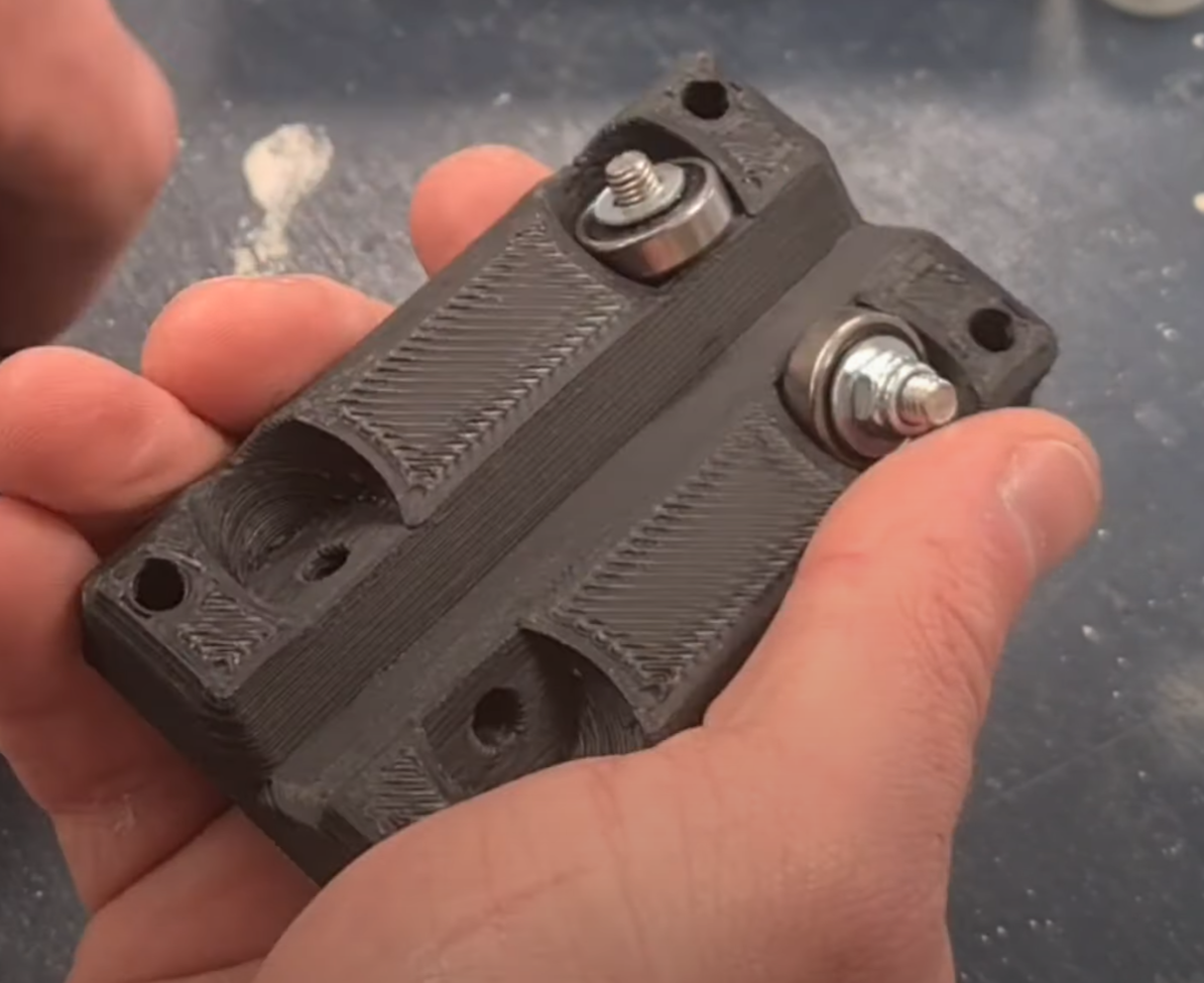
Insert the M5x20 HEX head bolts (4 for each carriage plate), then locate an M5 washer, 625 bearing, 2nd M5 washer, and finally an M5 Loc nut. Tighten nuts until just firm.
Don’t assemble the carriage plates on the 20mm square box sections just yet.
¶ Carriages Video reference
- R4L Part one 8:09 onwards
¶ Y Axis Sections
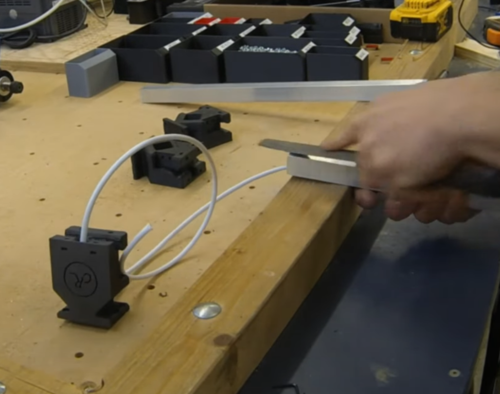
Note If you intend to mount endstop switches at the front of the Y rails, or include wiring for future accessories, remember to run your shielded cable through the box section rails and Y axis boxmounts BEFORE assembly.
Check the 4 box section lengths against the sizing spreadsheet for your planned build. Make sure each end is filed slightly to take the off the edges and corners that will be inserted into the 3D printed Y Axis boxmount. The Y axis rails will fit approx. 20mm inside each Y boxmount – do a pre-assembly check that the each rail with the 2 boxmounts attached will locate correctly on the baseboard holes. Lightly mark each rail 20mm in from the end to ensure proper seating. Using a mallet or wood block and hammer, knock the rail into each Y axis boxmount.
Don’t mount the Y rails just yet – its best to assemble a carriage onto each rail before you mount rails to the baseboard.
Video reference: R4L Part two Link 8:47 onwards
¶ Y Rails and Carriages
Now assemble a pair of carriage plates on each Y rail. Insert 4 M5x60mm Pan head bolts through the top carriage plate, an M5 washer and M5 nut on the other side, then the bottom carriage plate (on other side of the Y rail box section), then another M5 washer, and finally an M5 loc nut. When all 4 M5x60 bolts are in place, gently but firmly tighten the loc nuts. These need to be firm enough that the carriages sit firmly on the box sections with any rocking movement. Slide the assembled carriage back and forth and check each of the 4x625 bearings is moving smoothly – if one or more aren’t rolling properly, then consider tightening the respective bolt a little more.
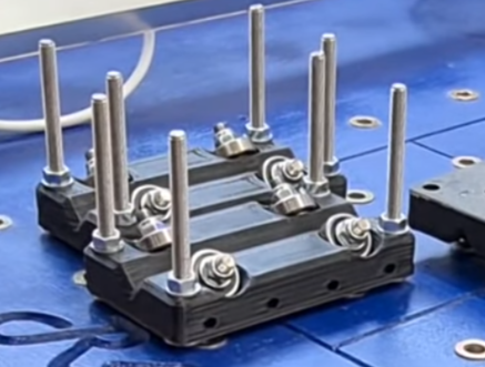
For the inward facing side of the carriages, it is worth seating M3 nuts in the various slots/cavities ready for later bolting to side panels and Z axis assembly. To do this, pop an M3 nut into the top or bottom carriage slots. Using an M3x30mm bolt, locate the nut onto the bolt, then tighten the bolt so the nut is pulled down into the hex-shaped cavity within the carriage. It is particular helpful to do this for panel-facing sides of the carriages. If any of the nuts don’t seat firmly, it might be helpful to put some masking tape over the nut slots to stop these escaping.
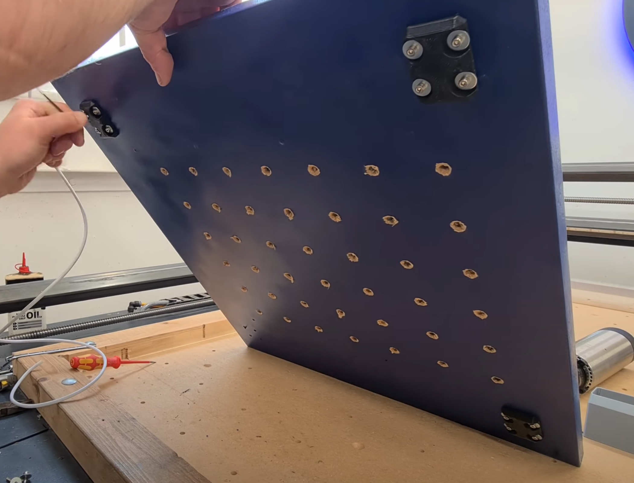
Only loosely tighten each M3 bolt. When both rail assemblies are mounted, check they are square on the baseboard and separated by the same distance at front and rear. When positioned correctly, firmly tighten each M3 bolt from under the baseboard.
¶ Y Rails and Carriages Video Reference
R4L Part three Link 7:22 onwards
¶ X Gantry Assembly
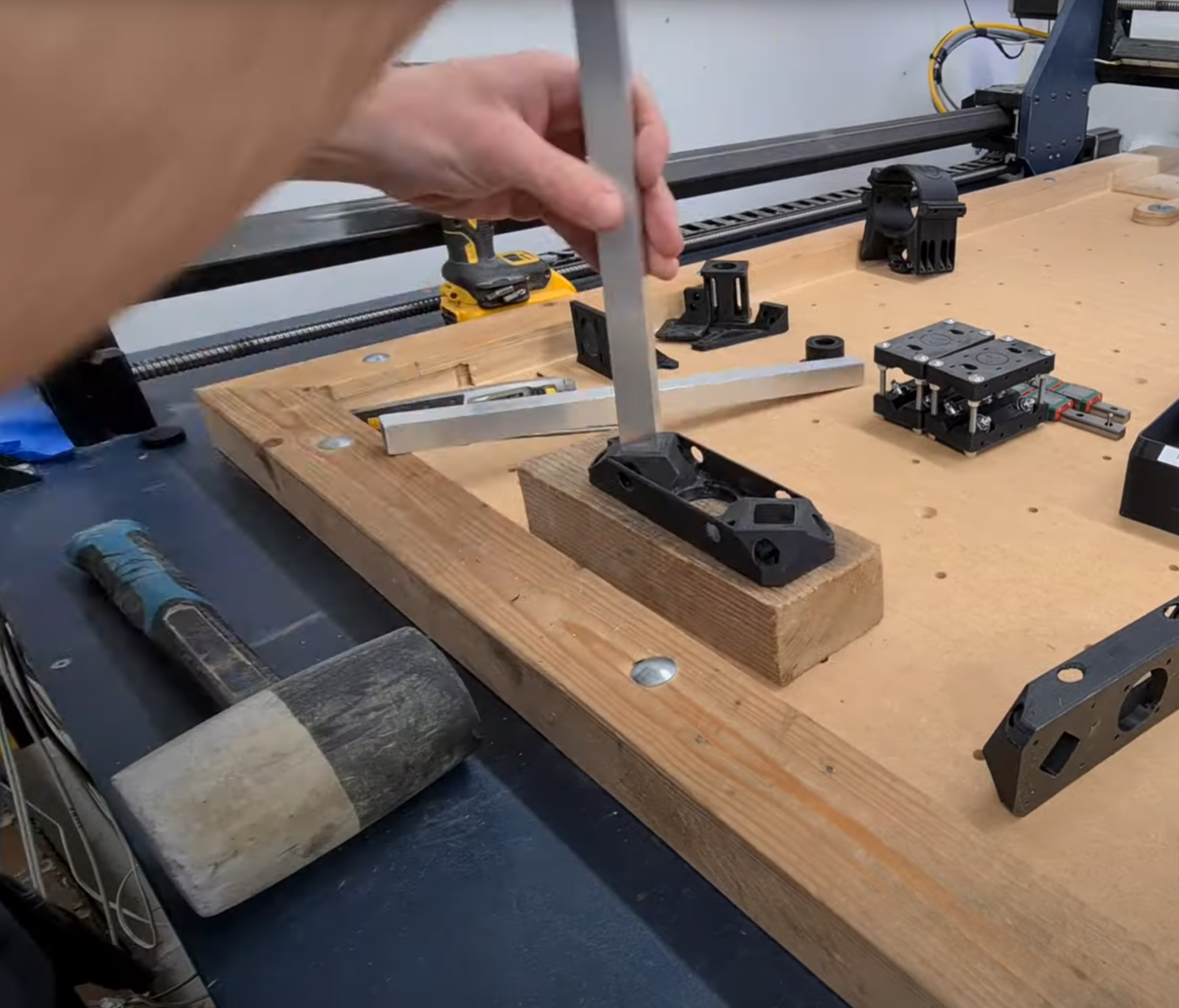
As per the Y rails, make sure there are no sharp corners or edges on each end of the X rails (box sections). Using a mallet, gently knock each X rail into a single X-axis boxmount, making sure the completely flat outside surface of the boxmount is facing out from the box section rails. Sit this out flat face on a block of wood when bumping in each X box section rail to ensure the end of the box section sits flush with the outside surface of the boxmount.
¶ X Gantry Rails Video Reference
X Gantry Rails R4L Part one LINK (9:30)
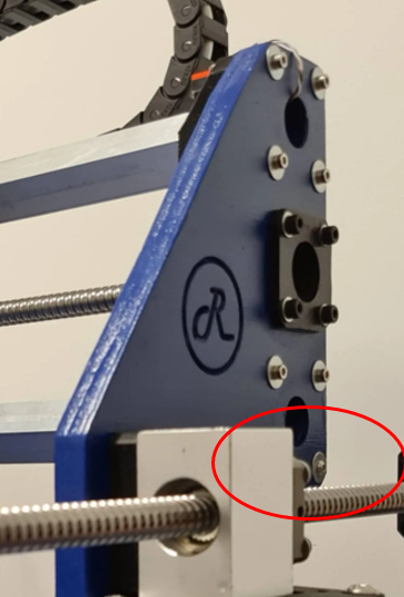
Note that one end of the X-axis boxmount has a hollowed out space where the X axis endstops will eventually be mounted (circled in red). This end will be pointing vertically UP.
Now go ahead and mount the remaining 2 carriages on the X rails. Just as you did for the Y rails, use M5x60mm Pan head bolts (bolt pointing downwards), M5 nuts, washers and loc nuts. It’s worth using loc nuts on the bottom to ensure the correct mounting pressure on the rails - and also protect against spindle vibrations shaking these loose which will minimize the need for constant maintenance.
Now is also a good time to drill and clean out the M3 holes on the gantry side facing the front of the machine and seat some M3 nuts in the carriage slots (again, same as previously done for the Y rails)
¶ Z Axis Linear Rail Mount Preparation
Drill/clean out the M3 holes for the linear rails and rear mounting holes on to the X gantry carriages. Check the orientation of your linear rails before bolting them to the Z carriage – if at all possible you want to very top of the linear rail to be flush with the top of the Mount assembly (so that when we later mount an FK10 bearing block on the top of the linear rail mount it will be able to sit flat).
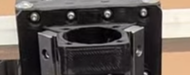
The top of the linear rails should be flush with the very top of the linear rail mount assembly, or just below.
Go ahead and mount the linear rails with M3x10 (or 8mm) bolts. Slide the cars on to the linear rails.
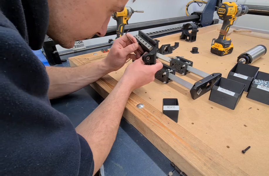
¶ Linear bearings Video Reference
Linear bearings being mounted R4L Part one LINK (10:26)
Use 2 long bolts temporarily for the bottom most holes on the linear rails – to stop the cars sliding off the rails during later stages, until we eventually mount the Z axis carriage to these.
¶ Mount the Z axis linear rail mount
Mount the Z axis linear rail mount to the X axis carriages. Make sure you have the rail mount orientated right way up (Large FK10 bearing mount facing upwards). Don’t be in a hurry to tighten down until all 16 bolts are seated loosely in their respective M3 nut, and the nut has retracted and seated into the carriage assembly so that it is held firmly and not rotating. Once all bolts and nuts are seated and firm, then proceed to tighten everything up. Slide a 608 bearing into the bottom bearing mount of the linear rail mount – you shouldn’t have to squeeze too hard to get this in – consider running some sandpaper around the inside of the bearing mount to remove any rough plastic if the bearing doesn’t slide into please easily.
¶ Attaching linear rail mount Video Reference
Attaching linear rail mount to X axis carriages R4L Part one LINK (11:51)
¶ Mounting the X Axis gantry to the Y rails
Attach each panel to the carriages on the Y rails using M3 bolts and washers – you should have previously installed and seated the M3 nuts inside the carriages, but if you didn’t do so now. Only loosely tighten each bolt, enough to ensure the corresponding M3 nut has retracted back into the carriage and not spinning. You may need to use a small screwdriver or allen key on some of these to stop them spinning until they tighten down properly into the recess inside the carriage.
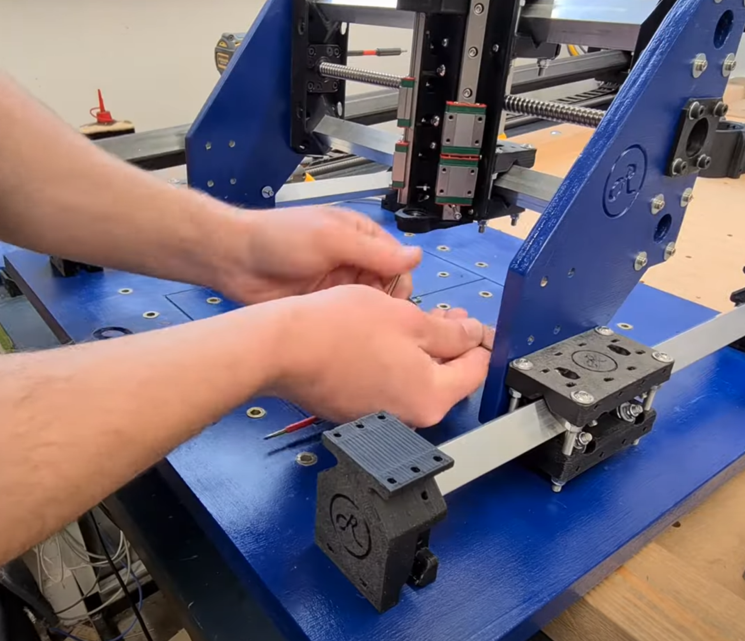
¶ Attaching X gantry to Y rails Video Reference
Attaching X gantry to Y rails - R4L Part three LINK (5:31)
Once all 16 bolts are in place, check the gantry is as close to vertical as possible, relative to the baseboard, using a large setsquare. Take your time doing this, as it will result in properly square machine later on. Check the X and Y rails are moving freely. Tighten down the M3 bolts attaching the side panels to the Y rail carriages.
If you left one Y rail only loosely tightened down on to the baseboard, now is the time to check again the Y rails are square and properly space to all the X gantry to slide smoothly fully forward and back. Once satisfied, tighten down the M3 bolts to firmly lock into position this Y rail. Don’t be too concerned if the machine isn’t perfectly square when the X gantry if fully forward or back – GRBL can autosquare out minor differences in the location of the Y rails and X gantry assemblies. Check again the bolts on the X gantry and those attaching the sides panels are all firmly tightened.
Congratulations – you’ve now got something that’s starting to look like a CNC!
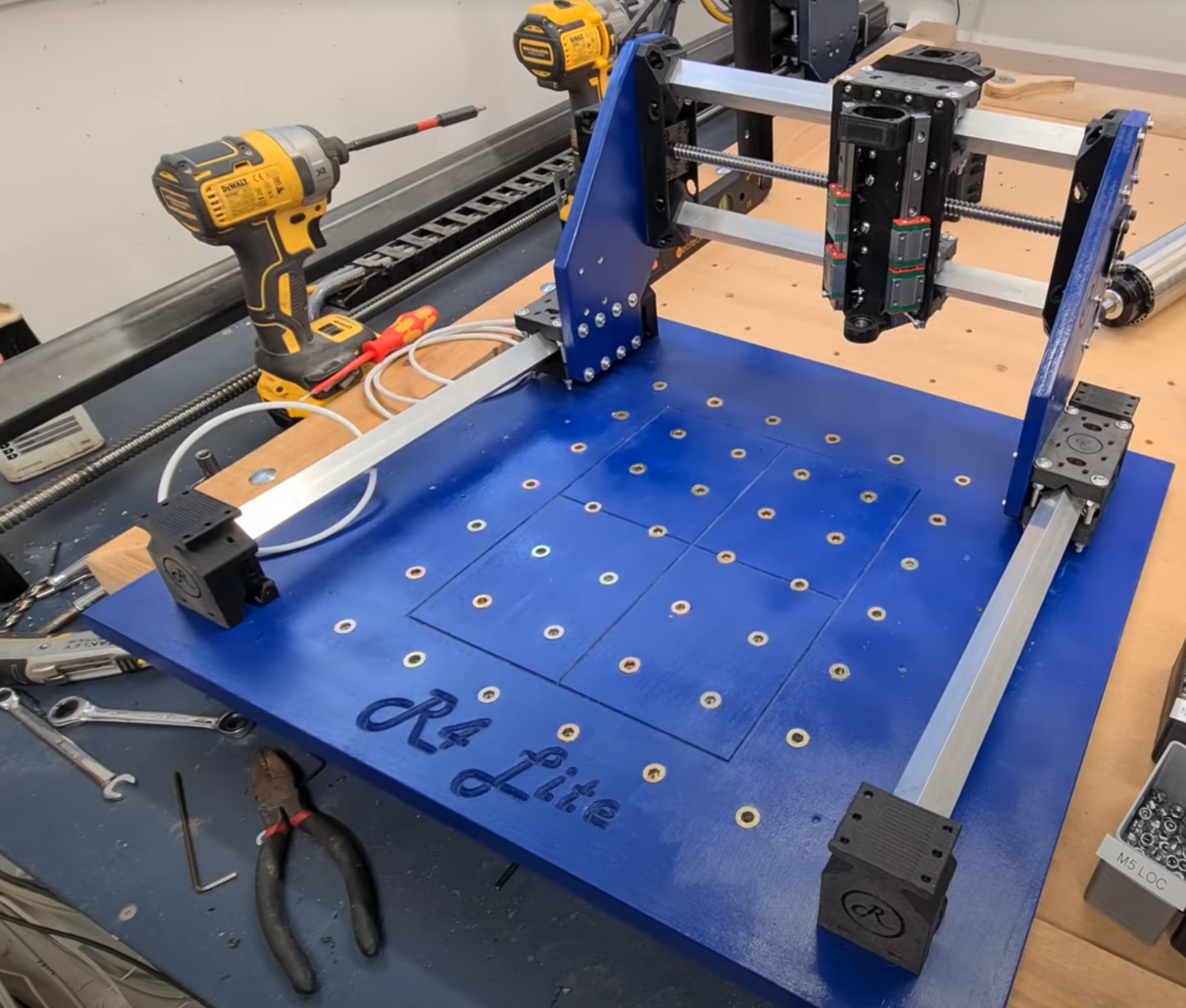
¶ Basic Motion Video Reference
End of R4L Part three LINK (note Pete has already installed the X axis ballscrew in the pic)
¶ Motion Assemblies
Now it’s time to mount the stepper motor assemblies and get them wired in to your chosen driver/electronics solution.
¶ Y Axis Motor Assemblies
Select a Y Axis motor mount and look closely at how it will orientate on top of the rear Y Axis Box mount. Note that the outside of one side in particular has a mounting to fit on to the box mount. Also note the motor mount is not symmetrical – the box mount flanges are closer to one end of the motor mount – that is the end that will point away from the stepper motor. Also think about the final orientation of your stepper motor wires – if you want these facing down towards the baseboard, make sure you take that into account when orientating and attaching your motor to the motor mount.
This is where extra long Allen keys will come in very handy. Mount the motor to the motor mount with M3 bolts and washers. I found some shorter M3x8mm bolts were handy here to make sure the bolts could be tightened down properly into the steppers. Watch closely to make sure yours are tight with no “slop” once all 4 bolts are in place.
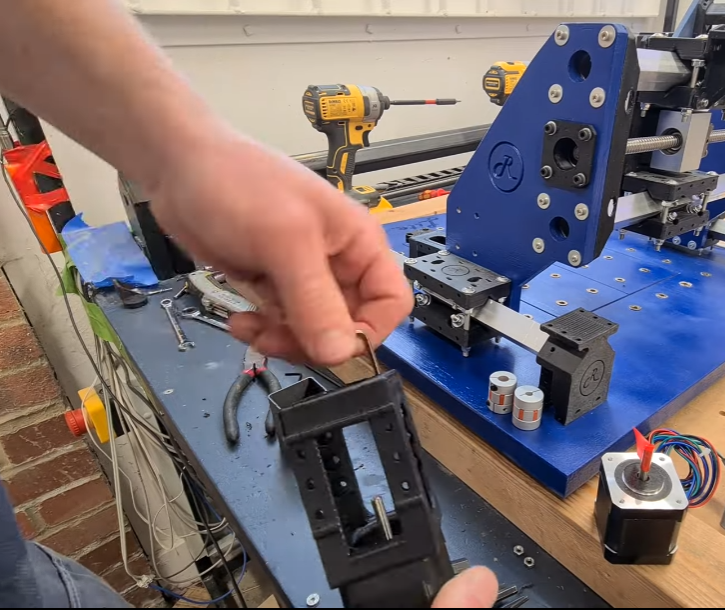
Slide a 5mm to 8mm coupler on to the stepper motor axle. Next it’s time to mount your first ballscrew assembly. Try to minimize how much you handle the screw. New ballscrews come vacuum sealed from the factory and shouldn’t need lubrication, but you might want to attach one end to a hand-drill and run the ballscrew carriage from one end back to the other, then back to middle, to check nice smooth motion and straightness before installation onto the CNC.
Slide an FK10 bearing on to the 8mm axle of the ballscrew, also slide on the small bearing retainer nut (as per pic below) and tighten the grub screw.
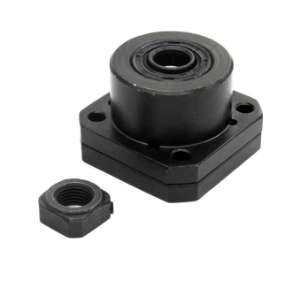
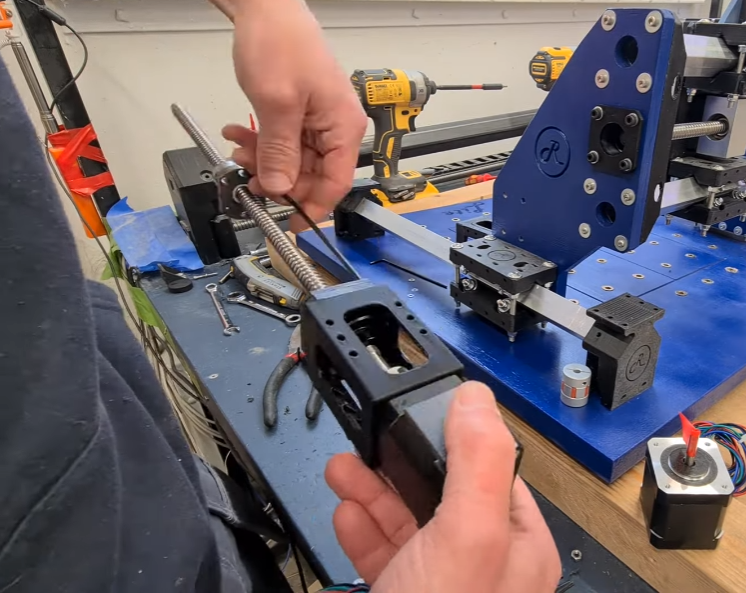
Attach the FK10 bearing to the motor mount with M4 bolts, washers and nuts. Note the orientation of the ballscrew - check again yours is pointing in the correct direction ready to be connected to the aluminium ballscrew mount (on the X/Z gantry) later on. To maximise the axis travel, you'll have to ensure the ballscrew nut is mounted in the directions of Pete’s video, that’s how this guide will describe assembly.
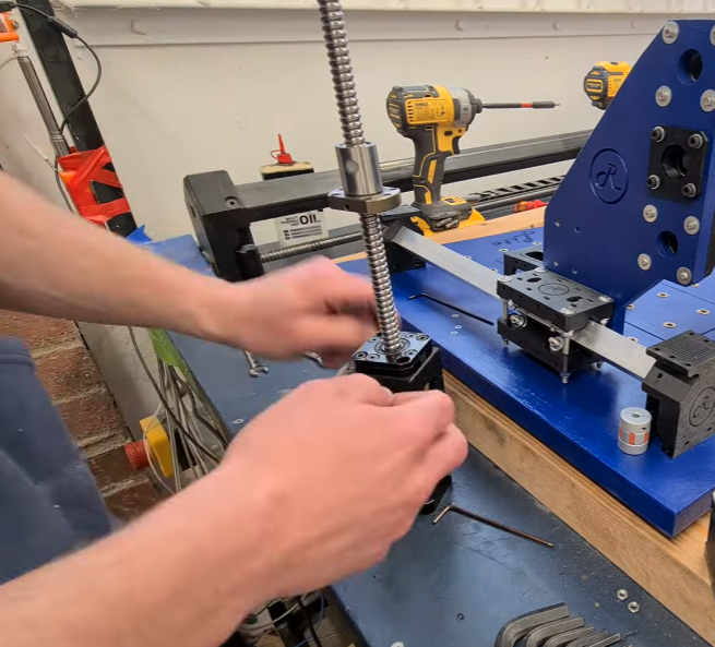
Install a 608 bearing into a Y axis idler and mount on top of each front Y axis box mount using M3 bolts, washers and screws. Install the aluminium ballscrew mount on top of a Y rail carriage. Make sure the mounting holes are pointing to the rear of the machine – attach to the side panel with M4 hardware. Leave these mounting bolts slightly loose for now.
Slide the ballscrew through the aluminium housing mount and slot the front end into the 608 bearing idler. Mount the Y motor housing down on the top of the rear Y axis boxmount using M3 hardware.
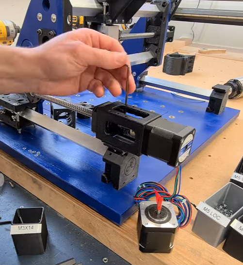
Now manually turn the ballscrew so the carriage is snug inside the aluminum housing/mount. Attach loosely with 6xM4 bolts and washers.
You should now have an entire Y axis motor assembly, loosely mounted. Check the ballscrew can turn freely, then gradually tighten down all the mounting hardware. Suggested order:
- Check the Idler mount on the front Y Axis boxmount is bolted down tightly and the bearing is seated correctly
- Tight the M4 bolts connecting the ballscrew carriage to the aluminium mount block
- Tighten the M4 hardware attaching the aluminium ballscrew housing/mount to the side panel
- Check the Y motor mount is tightly bolted down on top of its Y axis boxmount
- Check the FK10 bearing tensioner grub screw is tight
- Now tighten both sides of the 5mm to 8mm coupler connecting the stepper motor axle to the ballscrew axle.
When all of this is done you should be able to gently turn the ballscrew by hand and feel the X gantry moving smoothly forwards and backwards (as you manually move the opposite side of the gantry) without binding. If you do have binding, then consider loosening all the fittings and retaining bolts and trying again.
Now, repeat all these steps for the 2nd Y axis motor assembly. Take your time and double check the orientation of the motor on the motor mount so the stepper motor wires are pointing where you want them to go. Don’t be in a hurry to tighten down hardware until the end, to help ensure everything is aligned and able to move freely before we start powering up motors later on.
¶ X Axis Motor Assembly
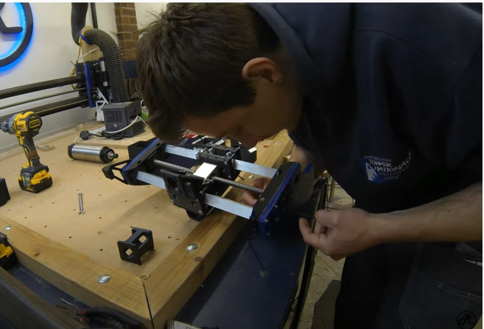
Armed with your new knowledge of ballscrews and motor mounts, now is a good time to install the X axis ballscrew and motor assembly. Pete does this in the 2nd assembly video, but makes some suggestions on how to do this in the easiest most efficient fashion, which we’ll try to take advantage of.
First install the X axis bearing idler on the right side of the gantry using M4 hardware. Next mount the X axis stepper motor on to its Motor Mount with M3 hardware, and slide on a coupler. The FK10 bearing on the left side of the gantry sits inside the left panel. The M4 mounting bolts will need to be long enough to fit through the bearing, side panel and into the motor mount on the other side. Slide the ballscrew into place in the aluminium housing mount and insert loosely into the FK10 bearing. Make sure you also slide the bearing retaining nut on to the ballscrew axle inside the motor mount.
Now it’s time to tighten the M4 hardware connecting the motor mount and FK10 bearing. Tighten the bearing retainer grub screw. Slide a 608 bearing into the bearing idler on the right side of the machine and install an 8mm circlip to hold the bearing in place.
Attach the ballscrew carriage to the aluminum mounting block (on the rear of the Z carriage) with 6xM4 hardware – don’t tighten these fully just yet. With the X axis motor and ballscrew assembly in place check the ballscrew can be turned manually with no binding. Once satisfied everything is ok, it’s time to tighten down. Suggested order:
-First tighten the 6xM4 bolts attaching the ballscrew to the aluminium housing mount
- Then tighten the M4 bolts attaching the aluminium mount to the Z axis linear rail mount
- Check the FK10 bearing and motor mount M4 bolts are tight, and the M3 bolts attaching the X axis stepper are tight
- Check the ballscrew bearing retaining nut grub screw is tight
- Finally tighten down the 5mm to 8mm coupler connecting the stepper motor axle to the ballscrew
¶ Video reference
Pete assembly X axis ballscrew assembly R4L Part two (5:30)
¶ Drag chain mounts
Attach the Y axis drag chain mount to the left Y axis carriage with M3 hardware. Install your chosen cabling into both dragchains, then connect both drag mounts to the Y and X axes with M3 hardware. You’ll need to shorten your drag chain accordingly to the size of your build.
Note: Make sure you have plenty of cable length to reach the Z carriage assembly – read through the Z carriage installation below first to be double-sure about this. Where in doubt, make the cables a bit longer than required between the motors/endstops and the control board connections.
Note: Make sure you have plenty of cable length to reach the Z carriage assembly – read through the Z carriage installation below first to be double-sure about this. Where in doubt, make the cables a bit longer than required between the motors/endstops and the control board connections.
¶ Z Carriage Wiring Preparation
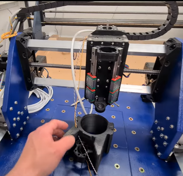
High quality shielded multi-core cable is recommended for endstop and motor wiring to minimize electrical interference with your movement signalling. Remove the outer cable shielding from the Z axis endstop wires. Twist approx. 20cm of exposed wires into a pair – Pete does this quite neatly using using a handrill. Take a photo of your wiring pairs so you can remember which colours are paired for which sensor when you later wire up the control board.
Ensure the Z carriages are clear of any stray plastic – drill out mounting holes gently and make sure the wiring cavities are clear by inserting a test wire.
Insert both wire pairs through the Z carriage, one pair each for the top and bottom endstop sensors:
¶ Z Carriage Endstop Wiring
A full description of wiring options is beyond the scope of this assembly guide. The reader is advised to avail themselves of Pete’s wiring info on the Wiki, and give some thought as whether you will be configuring your endstops as “normally closed” (NC) or “normally open” (NO), and possibly also if they will be set up serial or parallel. Both NC and NO have advantages and disadvantages in terms of safety, ease of configuration, etc. It is recommended you do some test wiring and connection to your chosen control board and software ecosystem before wiring up the Z carriage to make you know which connectors you will be using on the endstop switches, if your control board responds correctly to your chosen NC/NO configuration, etc.
The Z carriage area is a very tight working environment. It was elegantly designed to fit as much hardware functionality as possible into a small space, and with minimal X width (to maximize the working width of your CNC in the X axis). The trade off is assembly at this point is tight and a bit tricky - so take work carefully and check assembly at each step.
Try to anticipate the length of endstop wires you need to have no tight spots, but also not excessive loops that risk getting caught. Cut each pair to the chosen length. Slide a short length of appropriate sized shrink wrap over the wire pair, then solder each wire to the appropriate sensor terminals. Slide the shrink wrap over the connection and apply heat to protect the connection.
Loosely attach each endstop in its final position with appropriate small bolts, making sure the wire pairs are safely routed back into the carriage.
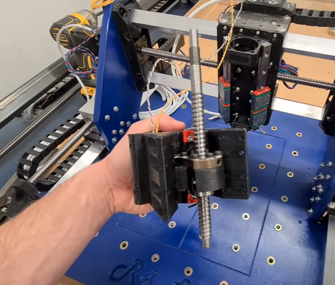
Install the Z axis ballscrew, attaching the ballscrew carriage down into the Z carriage with M4 hardware. Consider avoiding washers for the bolts closest to the X rails - to avoid any protrusions that might rub against the assembled Z axis linear rail mount. Leave the M4 bolts only loosely tight for now. Once the ballscrew is in place, tighten up the bolts on the endstops.
¶ Installing the Z Carriage
Slot the bottom of the Z ballscrew into the lower 608 bearing with the top of the axle protruding through the FK10 bearing mount. Connect the FK10 bearing with M4 hardware, and install the bearing retaining nut on top.
The nuts for the M4 bolts attaching this top FK10 bearing are seated inside the top of the linear rail assembly and may be tricky to keep in place (without falling down into the insides of your Z carriage assembly). It is worthwhile seating these before you actually insert and attach the bearing block – install the nut and washer underneath and gently tighten an M4 bolt from the top until the M4 nut pulls up into the linear rail assembly and is seated firmly. When it is time to later install the FK10 bearing, very carefully install the M4 bolts so you don’t knock out these pre-seated M4 nuts. It may also help to use some “Blu-tack” behind the M4 nuts to further reduce the chance of these nut falling down during bear assembly.
Next loosely fit the 16xM3 bolts on each side of the Z carriage through into the linear rail blocks. Make sure these are the right length so you can tighten them down firmly at the end (e.g. consider having some M3x8mm bolts on hand if M3x10 is too long for your rail block threads).
Manually run the Z axis ballscrew back and forth through its full reach of movement checking for any binding. The two extra long M3 bolts we used at the bottom of the linear rail can be replaced with their correct final shorter size now. Suggested order for tightening down Z axis hardware:
- M3 bolts connecting Z carriage to rail carriages
- Tightening of M4 bolts on FK10 bearing
- Grub screw on top FK10 bearing nut retainer
- Final tightening of M4 bolts connecting ballscrew carriage to Z carriage
Don’t rush these steps – if the Z axis ballscrew isn’t turning freely you risk losing motor steps or belt control during operation of the Z axis. If you can’t turn the ball screw smoothly and easily, repeat the process to try again.
Install the Z axis motor with M3 hardware. Connect the appropriate bore pulley gear to both the Z axis motor and top of the Z axis ballscrew. Install the belt, and adjust the location of the Z motor such that the belt is firm and tight. Tighten Z motor hardware in position.
Install the four accessory rail knurled nuts on the Z carriage, along with the 4xM3 bolts for tightening the spindle mount. Check the spindle/router can be installed and held in place straight and firm. You may need to shim the router inside the Z carriage later on to ensure it is properly square with the machine and baseplate. Manually move the Z axis through its full range of motion and again check nothing is binding or rubbing.
¶ Install Remaining Wiring
As per Pete’s wiring guide, connect the X, Y and Z axis motors to your control board. Thread cabling through the X gantry and wire up the Min and Max X axis endstops (again, according to your chosen method of NO, NC operation). Install and wire the Y axis endstops, running and attaching cabling under the baseboard as required.
Wire up your spindle with fully shielded cable. If you are using a router instead of a spindle, consider using cable ties to safely route the power lead back along the X axis gantry and off the side of the machine.
¶ Final wiring and commissioning tests
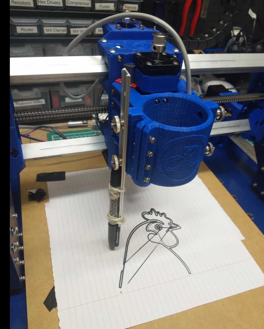
CNC newbies will still have lots to learn about CAD, CAM and gcode sending software, wasteboard installation and how to clamp your work. The journey has only just begun . For your very first motion tests consider attaching a felt pen to the Z carriage and checking you have free and reliable motion of all axes sufficient to draw an appropriately scaled SVG vector graphic.
Please share your build experience and photos on the Root Discord, and don’t be afraid to suggest improvements to the Root CNC Wiki.
Finally, locate a cold beer and sit back to celebrate and survey your fully operational Death Star, Root 4 Lite CNC.
Massive thank you for Robs contribution to the wiki!
¶ Support the Wiki!
If you would like to support the project and provide information on specific machines, then please check this page out first. Failing that, please let me know which area you want to contribute to and I can add your information to help others out!
¶ Social links
- Facebook Group
- Discourse
- Discord Great for quick answer to questions
- Thingiverse
- Youtube