¶ Introduction

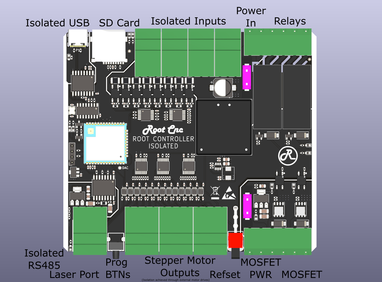
At its core the Root controller is a ESP32 GRBL isolated motion controller (FluidNC/ grblHAL). What makes this controller different is the focus of providing isolated IO to the CNC controller. The controller is designed to accommodate a wide range of operating conditions and machines, to provide ultimate flexibility (its not just a Root CNC Controller).
The controller is designed to isolate the key area of the design to mitigate any nuisance issues when operating in an electrically noisy environment. The design isolates the following areas from one another: Steppers driver outputs (achieved by using externally OPTO isolated drivers), USB, Relays, MOSFETs and RS485. Perfectly suited for the larger CNC machines.
¶ Key features
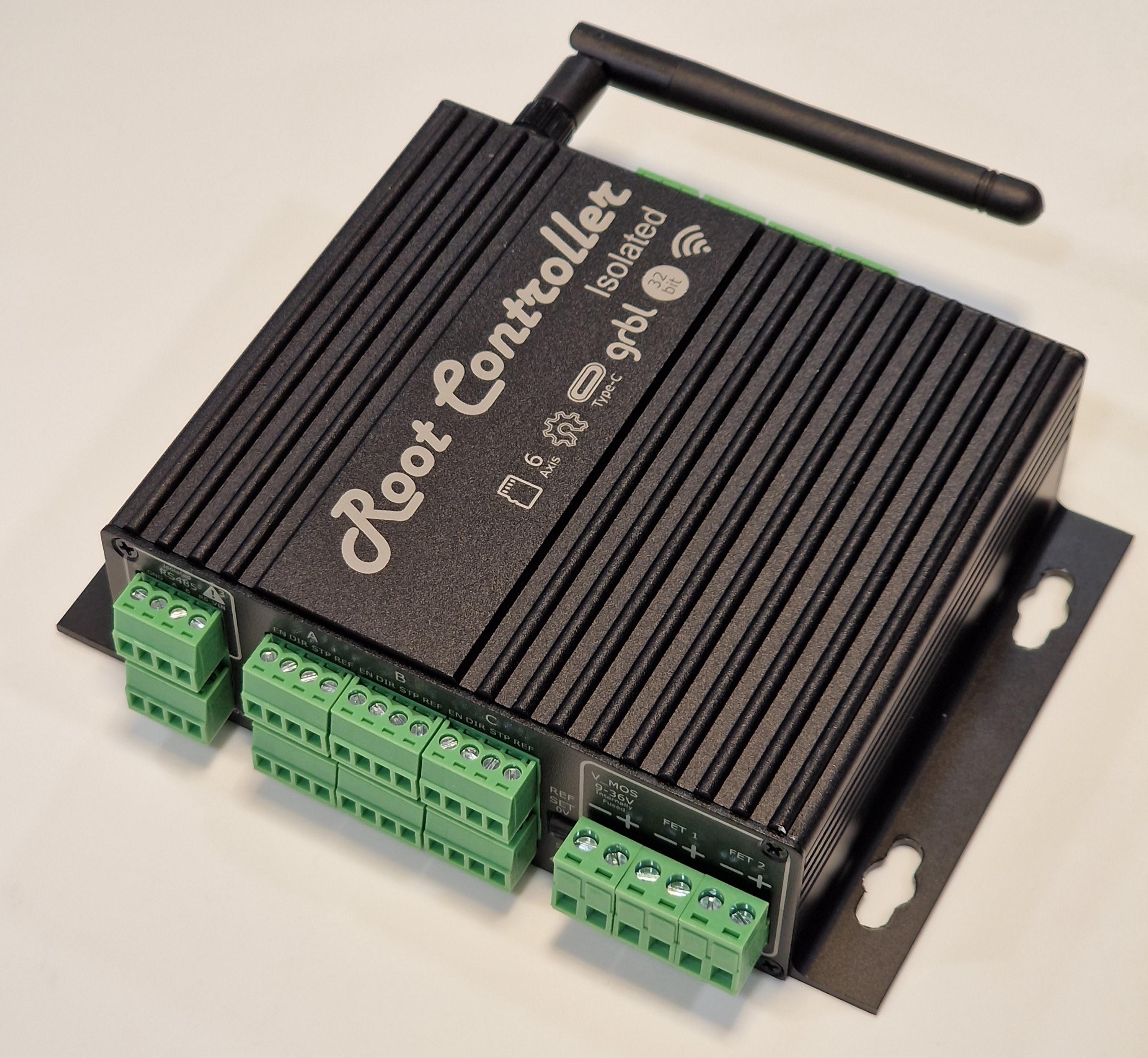
- 6 axis motion control (Axis ganging can be done via software - 18 digital outputs, can be repurposed)
- Wide input voltage range (9-36V)
- WiFi or bluetooth support for remote control and job loading
- SD card
- 8 Isolated inputs (supporting NPN inductive switches and Standard NC/NO switches)
- 2 Isolated Relay outputs for switching high voltage outputs, say a compressor
- 2 isolated MOSFET, perfect for driving solenoids for coolant or mist
- Dedicated Laser output port.
- Isolated USB
- Isolated RS485 (Modbus serial port)
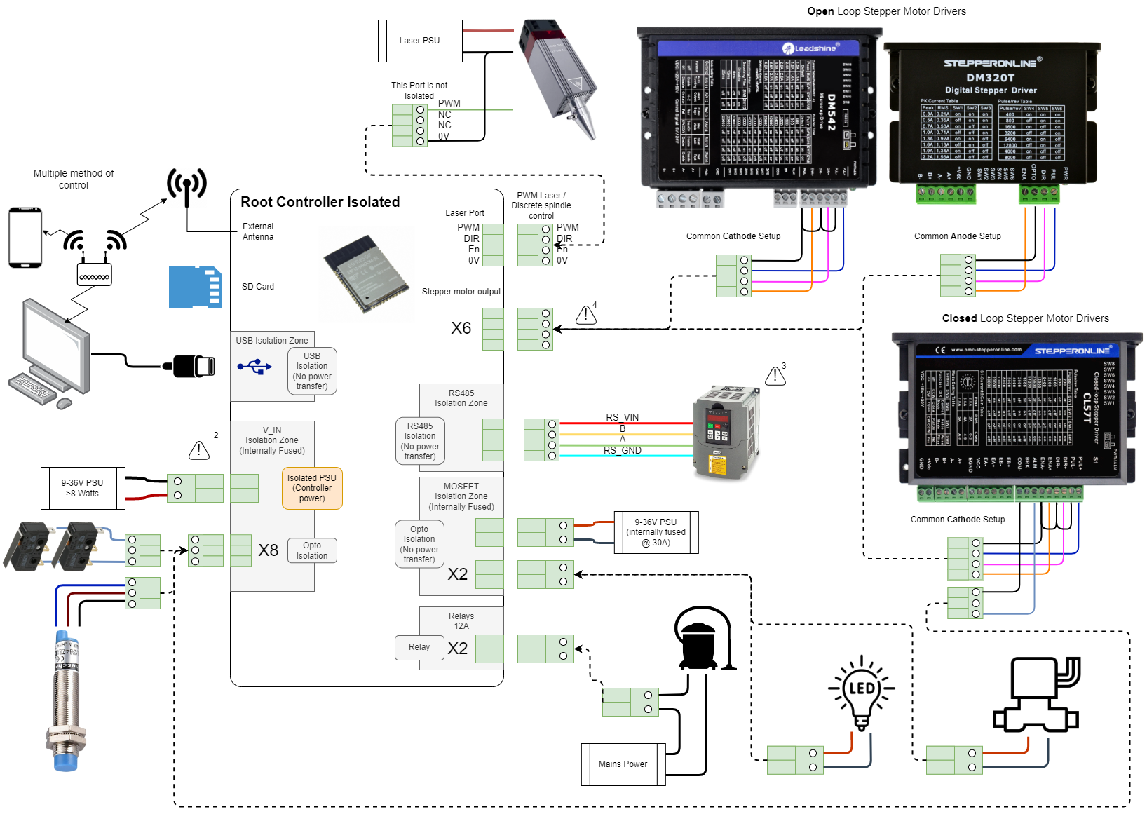
¶ Block Diagram
¶ Demo Video
Click Image to load youtube video
¶ Power
The Root controller is segregation into multiple isolation zones to suit the individual needs of the CNC builder. The purpose of these zones is to help isolated areas from interfering with one another. For example the spindle control vs the low noise CNC controller zones. The Root controller is well suited for large CNC machines and plasma cutters.
Carefully consideration should be made when planning the electronics for your CNC machine. As optimal performance is dependent on the type of machine you are building. The information below will aid your design. If you feel information is missing, please send me a message and I’ll clarify and aid you.
The controller has the following major areas of isolation:
V_in ISO- this is used for all inputs and powering the CNC motion controller.RS-485 isolation zone- this provides an isolated RS485 interface to talk to your VFD or other peripherals (more items will be added in the future). This zone is typically powered by the VFD and doesn’t require any additional interfaces or PSUsMOSFET isolation- this is a separation isolated zone which comprised of three high power MOSFETs. This is powered from a separate power input and is perfect for controlling device which need power, for example Solenoids, lights etcController reference- this area is not isolated to the CNC controller. isolation is achieved through the OPTO isolated stepper motor drivers. The laser/ spindle port is also referenced to this area. when using this port, careful consider is required to ensure the other isolation zones are not violated.Relay zone- three relay outputs are inherently isolated from everything else and between them self.USB ISO- the usb type C connector is isolated from the controller to ensure. This is perfect to ensure your expensive laptop or CNC computer is not directly attached to your machine, this help mitigate fault propagation effecting you machine.
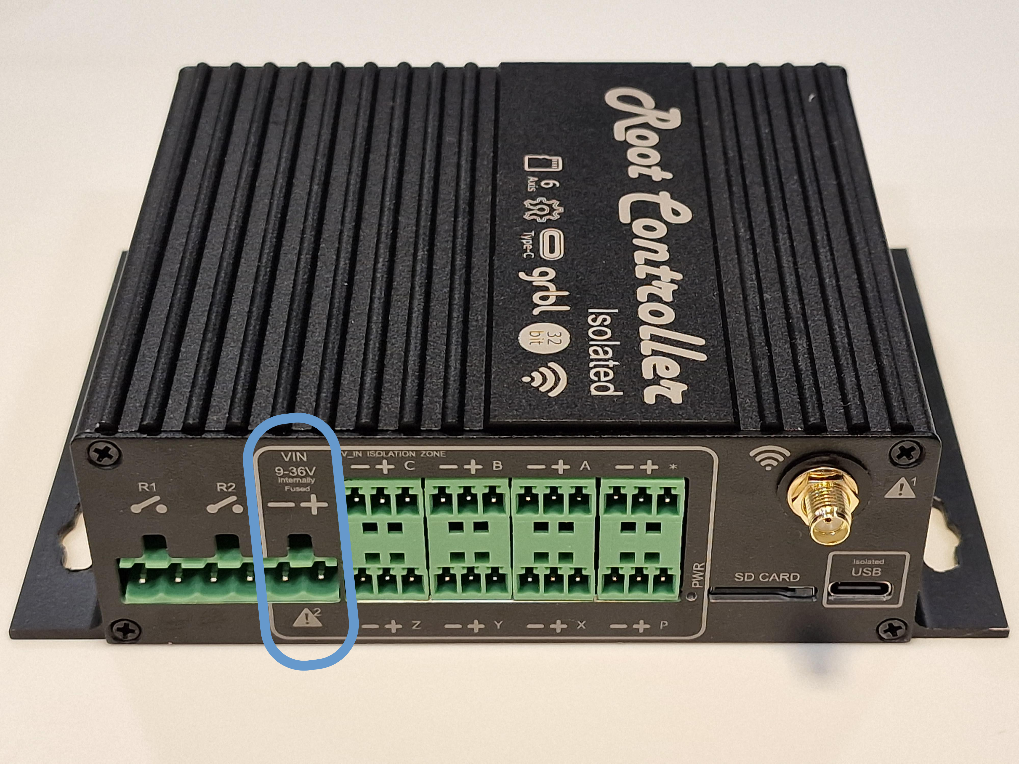
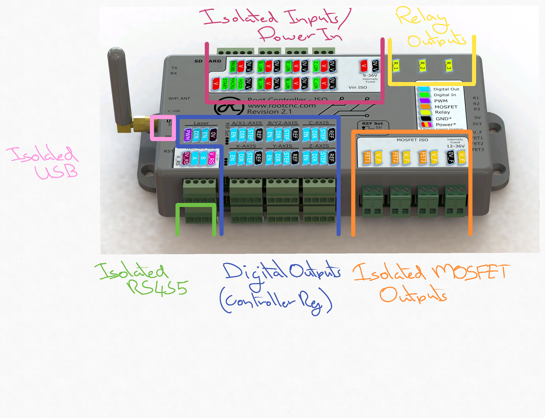
To ensure optimal performance and noise immunity - please ensure the current return paths and loops are reduced and power zone references are not connected together. E.g. avoid connecting
0Vto0V_V
¶ Powering the controller
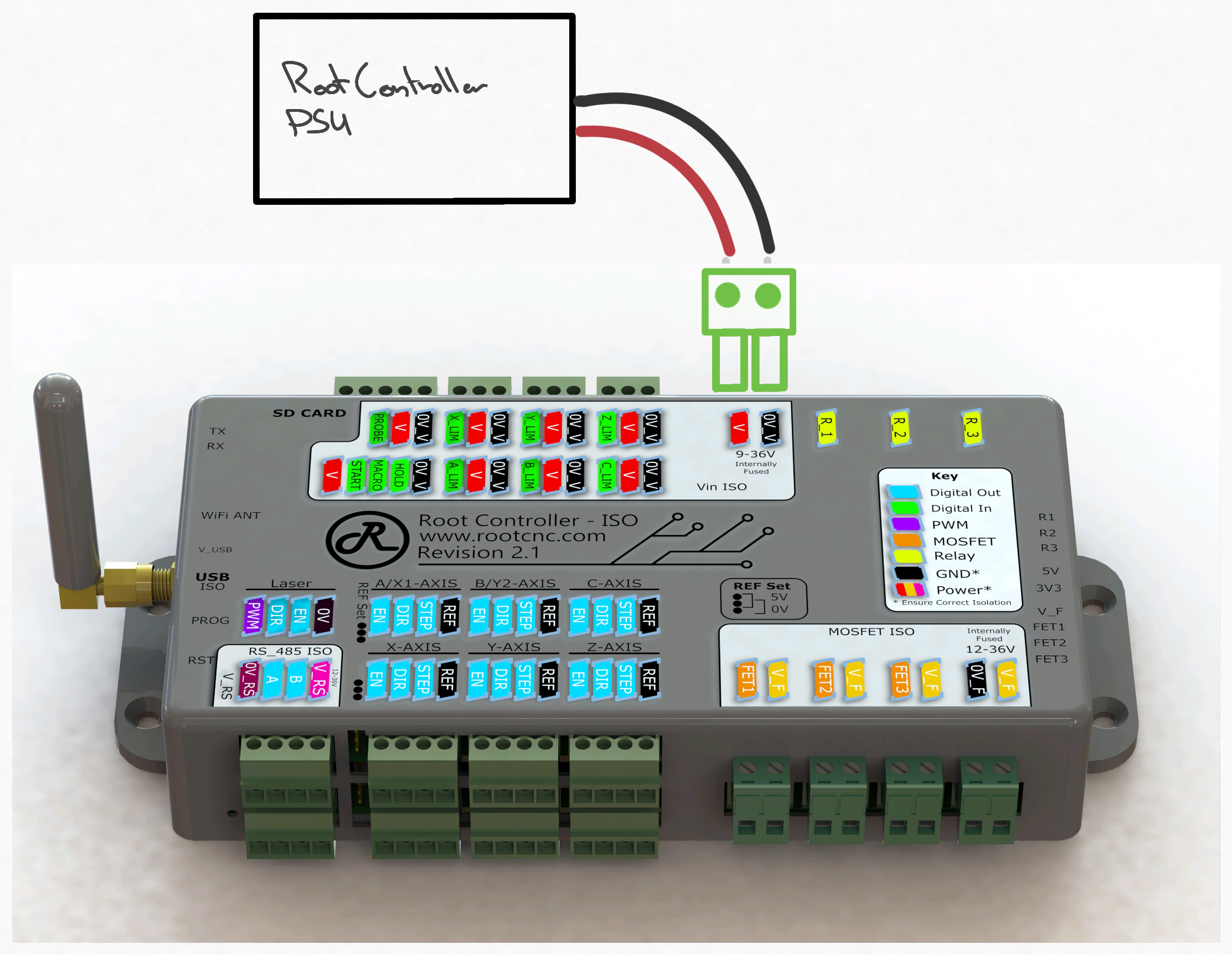
Power is applied through the power in connector in the Vin ISO zone. The input requires a supply voltage of anything between 12-36v.
This power supply is internally fused for added protection.
The minimum PSU capacity should greater then 8 watts to power the controller.
The voltage applied to the controller through this connector is also applied to the controllers inputs power pins. This is useful when powering external sensors, such as inductive probes. The inputs power pins are fused with the same fuse as the main input power connector.

¶ Stepper control
The Root Controller is specifically designed to control OPTO isolated external stepper motor drivers. The reason for this is due to their high current demands of their logic inputs on the motor driver, these are typically around 10-20mA per input (enable signals are typically lower as these do tend not to toggle). These sort of current demands normally exceeds the max electronic IC package current. Exceeding these values can impact the life of the electronic products - the Root controller ISO has been designed to take this into account and will happily supply the max current across all its outputs and provide a long life for the electronics.
The Root controller Rev 2.1 and onwards supports both common Anode and common Cathode external motor drivers, with the use of the ref set settings.
| Drive type | Rev 3 | Rev 2.1 | Rev 2.0 |
|---|---|---|---|
| Common Annode | Yes | Yes | NO |
| Common Cathode | Yes | Yes | Yes |
Some drivers might expose both anode and cathode per input, if this is the case then the wiring will need to be configured into either common anode or common cathode. please see example wiring configurations for more information
¶ Stepper Driver Outputs
The Root controller support six software configurable stepper motor outputs. These are accessable via a 4 port connector, which are wired identically.
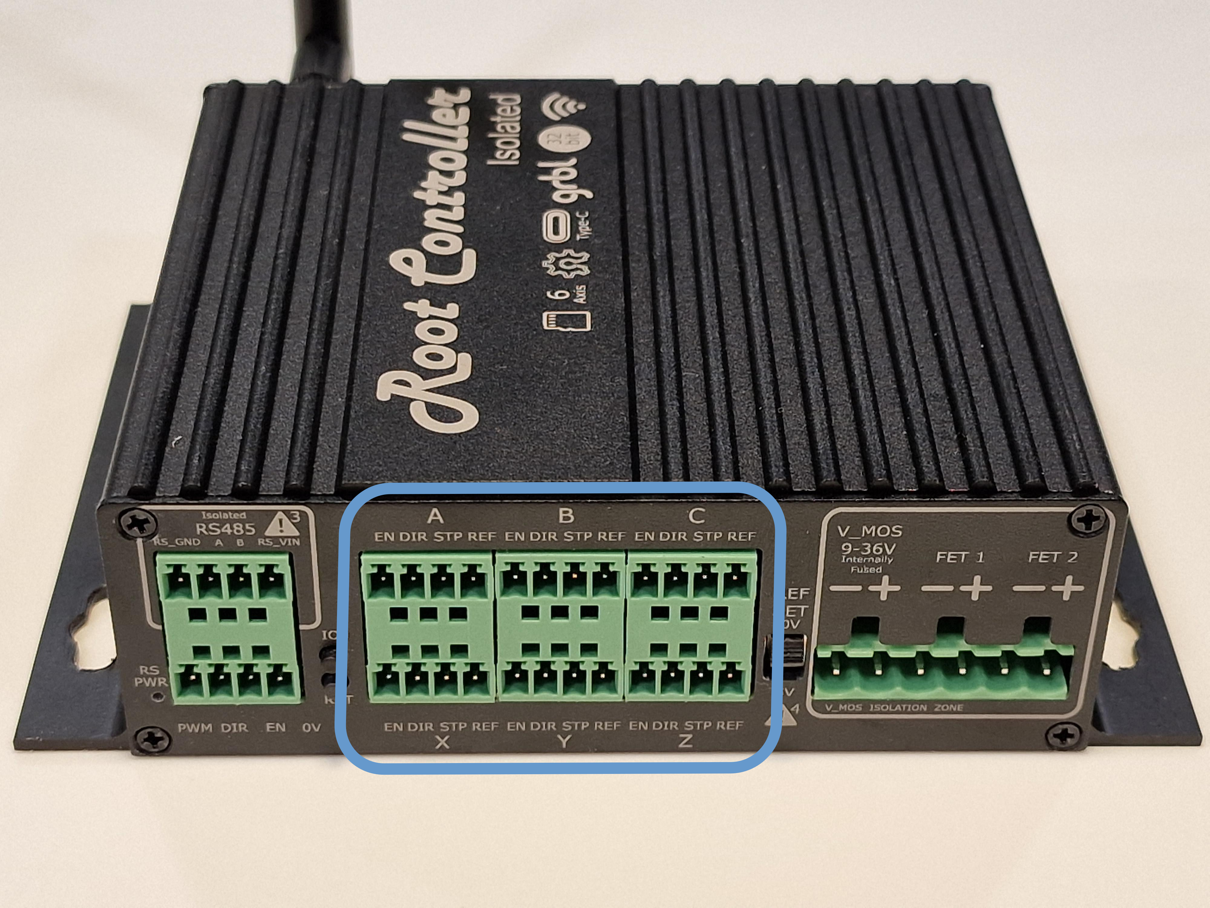
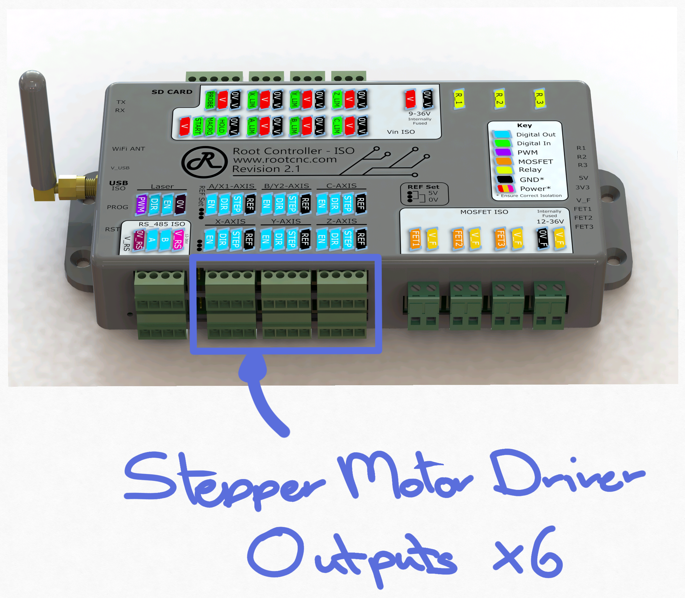
When not using these ports for the stepper motor controller, then the remaining ports can be reconfigured in software to support discrete outputs.
¶ Ref Set
The Root Controller has two configurable references, either 0V or 5V to set the refernece point for either common anode or cathode stepper motor wiring. please ensure these are correctly configured. More information below. (Rev 2.1 and onwards)
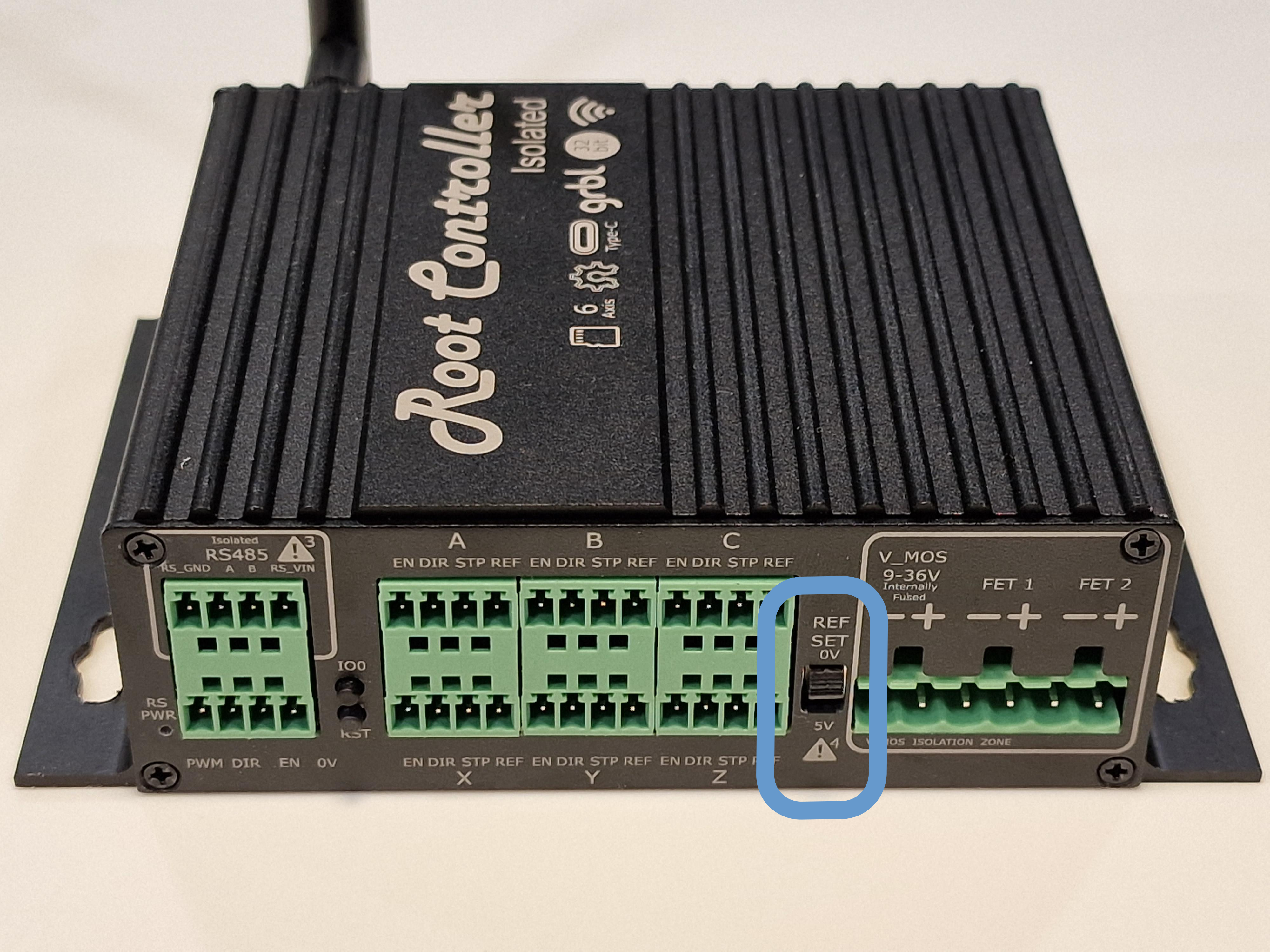
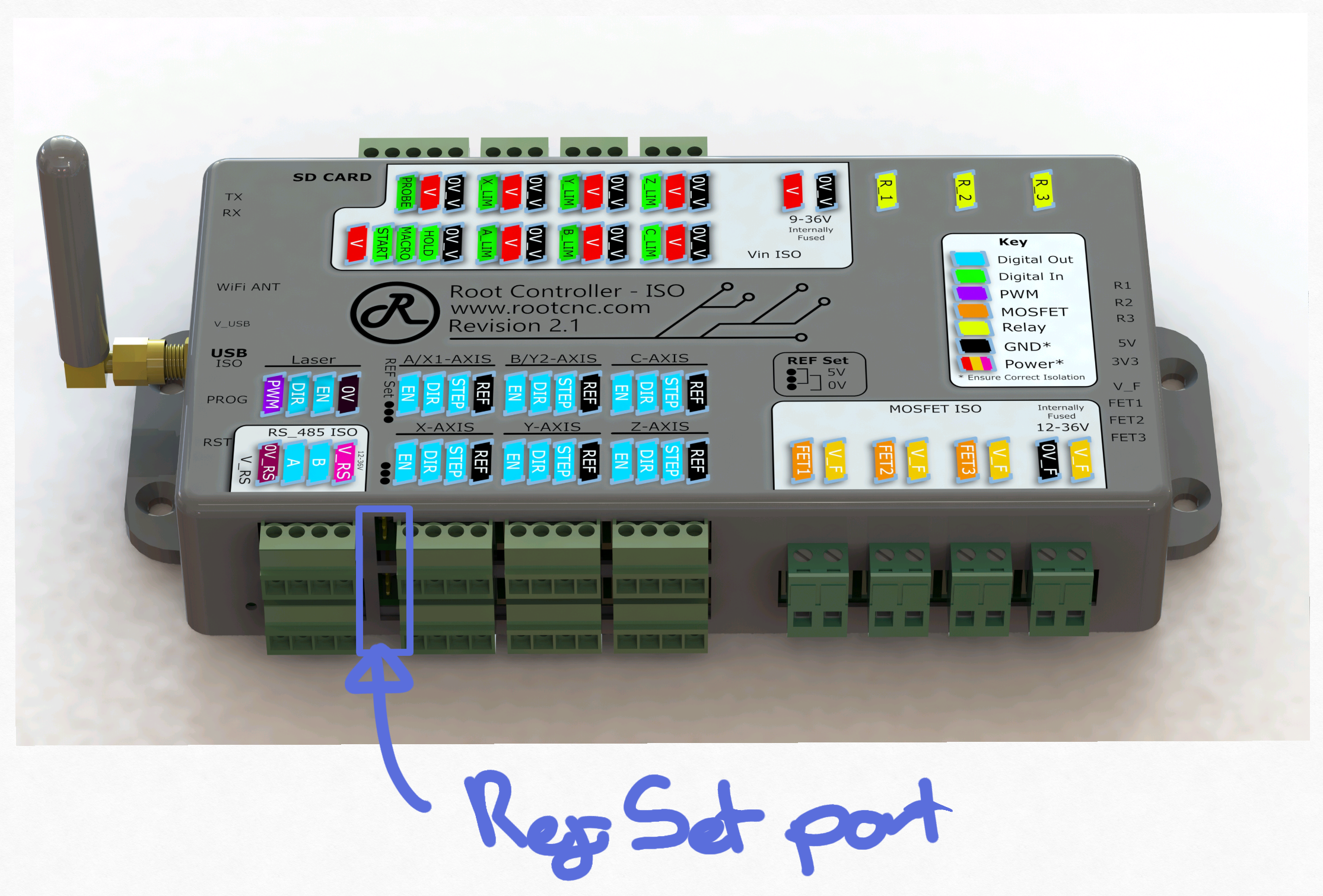
Both headers on the Root Controller need to be set correctly in order for correct operation, these are denoted as ref set on the controller label. You can mix the top and bottom reference points but you’ll need to ensure the three outputs per layer are set correctly with the corresponding outputs. Its recommended to set the ref set points to same configurations.
- Ref set 1 - sets the reference point for axis outputs X, Y, Z
- Ref set 2 - sets the reference point for axis outputs A, B, C
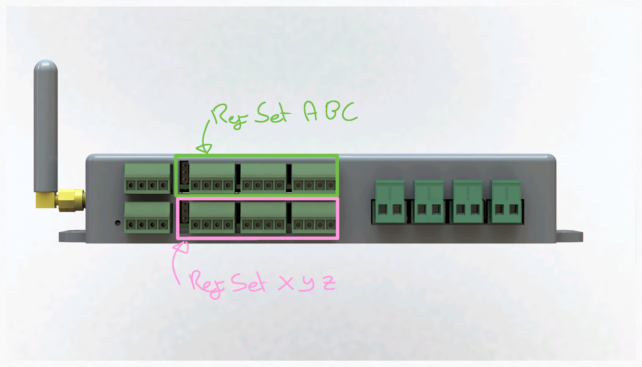
Please note these outputs are software configurable. The Root 3 onwards will use either axis outputs of A, B, C to be the second Y (YII) axis. If you are planning on using the root controller for other style of machines; the software supports up to two outputs per axis. For example the MPCNC Which has XII and YII which will use ports A,B.
Rev 2.0only supports a common cathode (0V reference)
Beta card can accommodate both common anode and common cathode by default
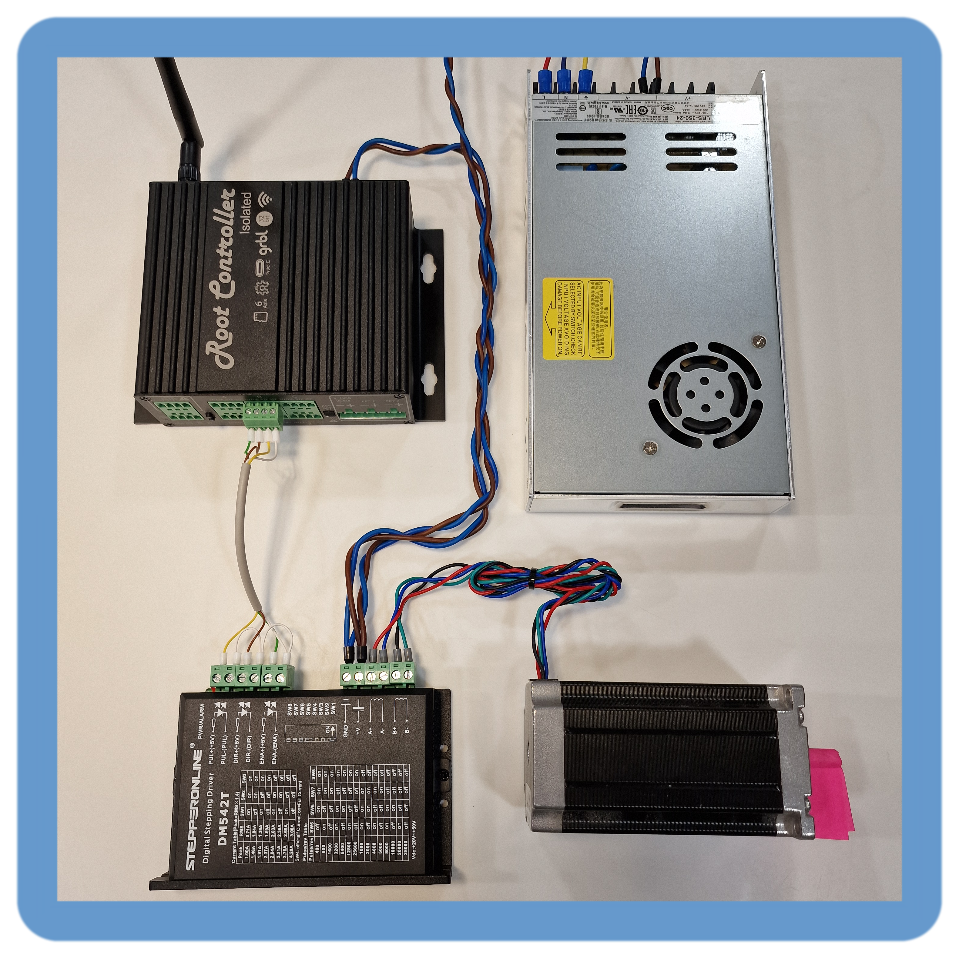
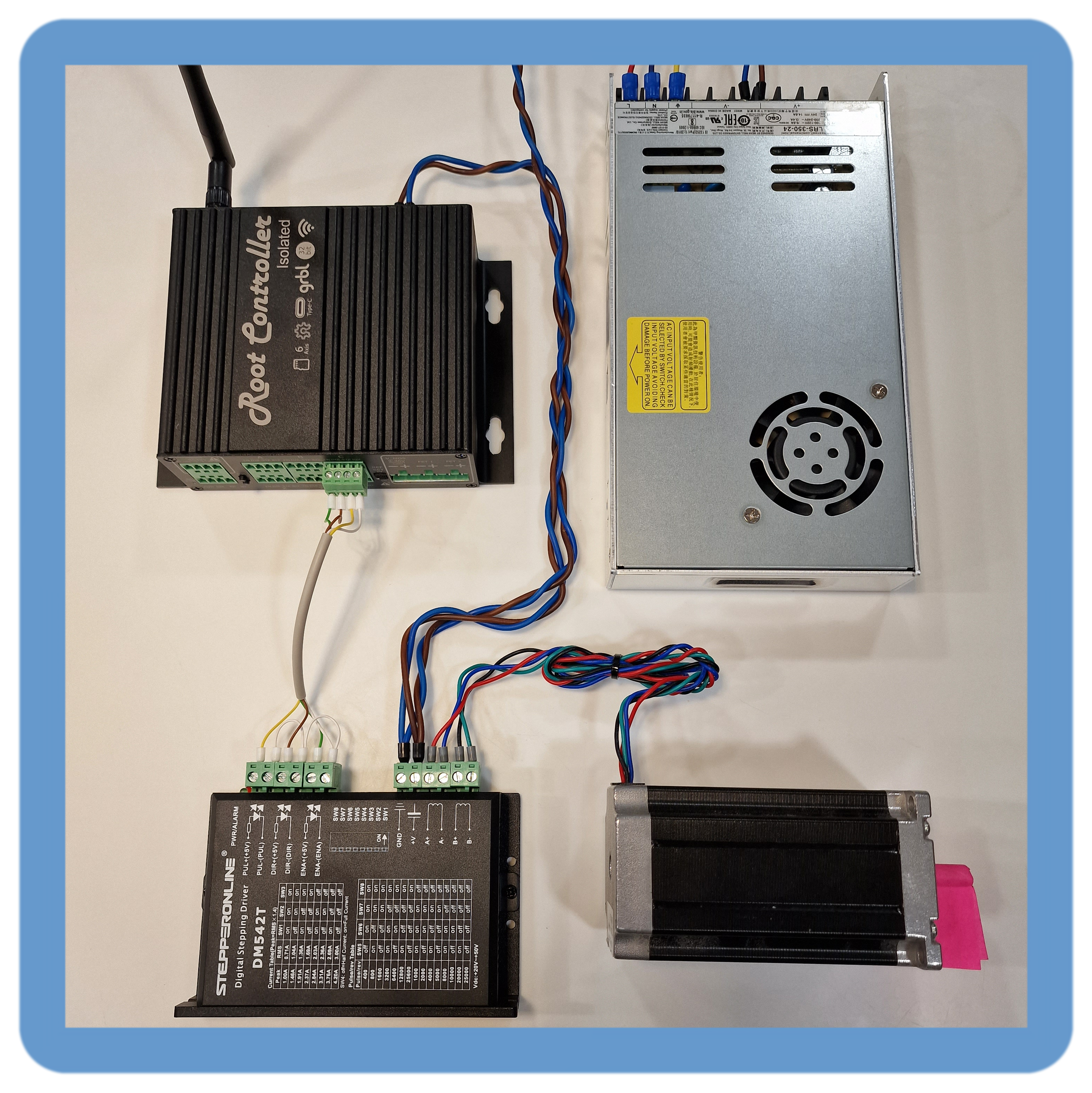
¶ Stepper Motor Driver Wiring
¶ 5V reference (Common Anode)
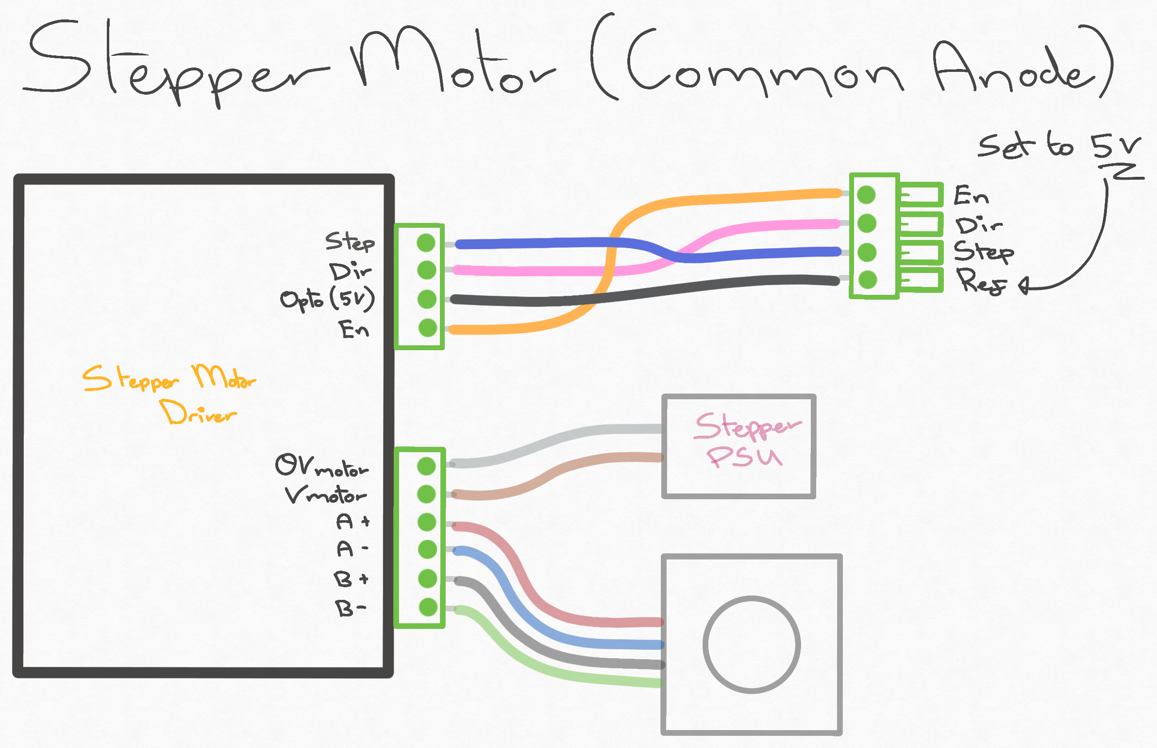
Below is a list of known external motor drivers to work in the common anode configuration:
- DM320
- DM332
Using this configuration results in the logic being inverted - please configure the software to be either Rising or falling edge triggered or your machine could be half a step out continuously
¶ 0V reference (Common Cathode)
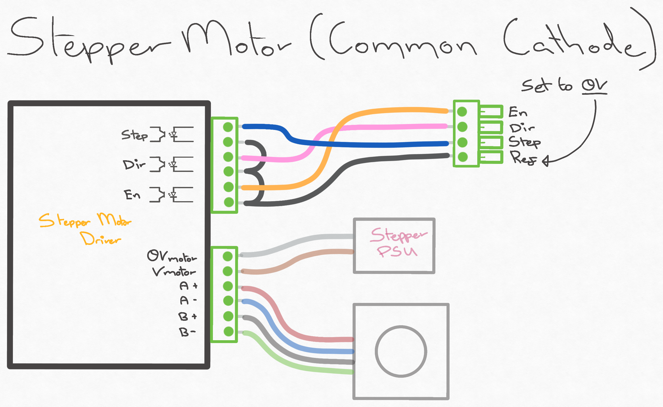
Below is a list of known external motor driver to work in the common cathode arrangement
My Root 4 and 4 Lite both use the common cathode setup
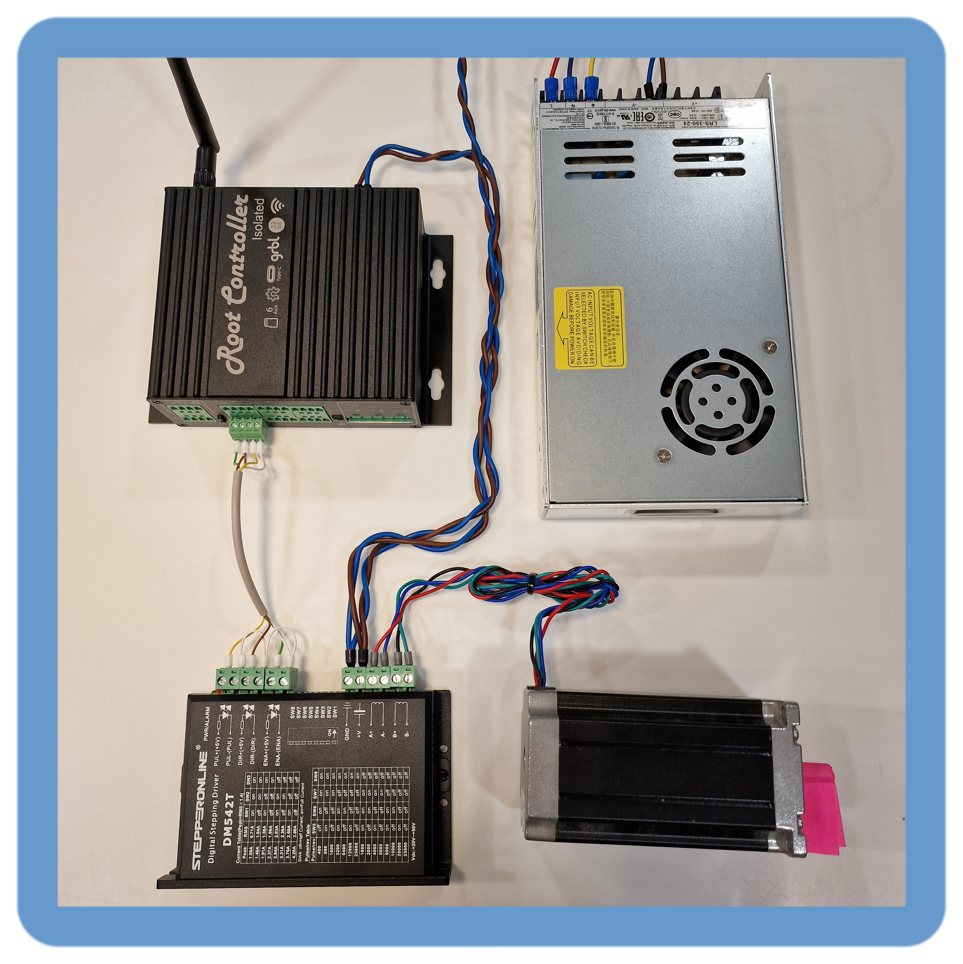
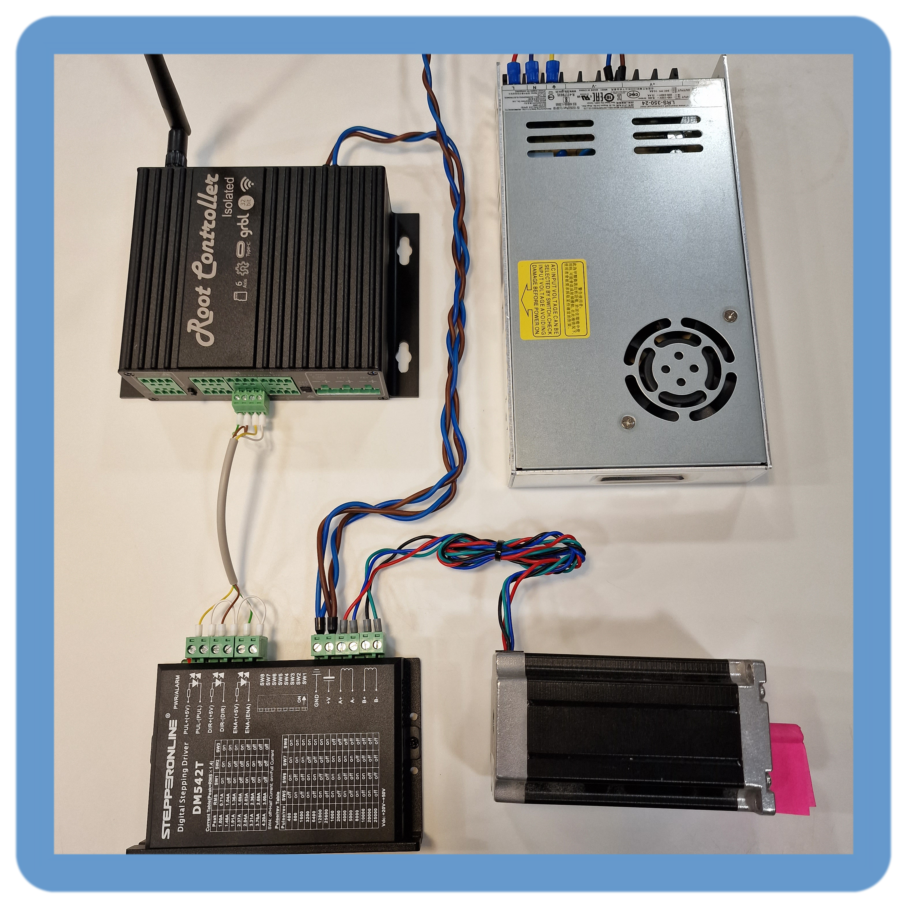
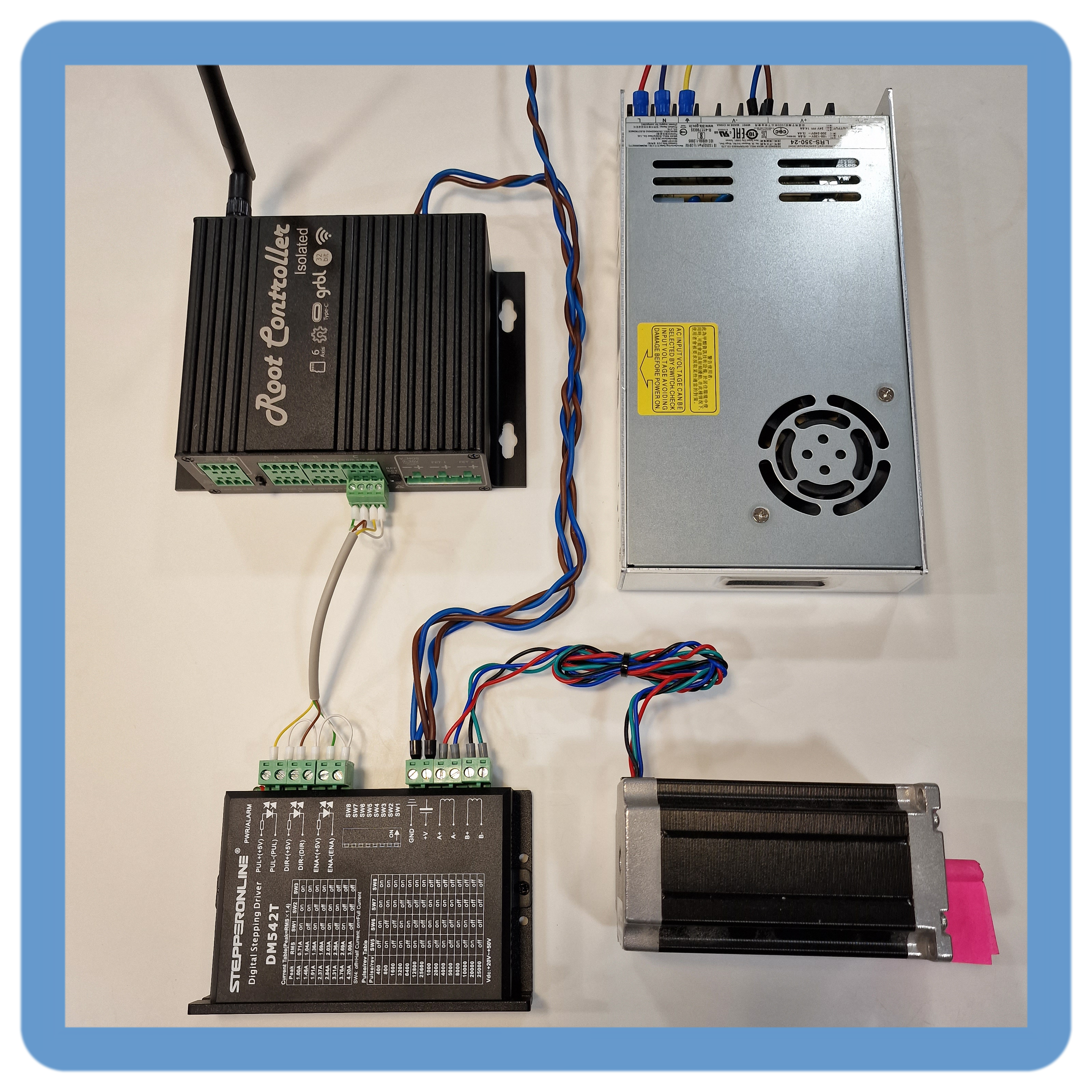
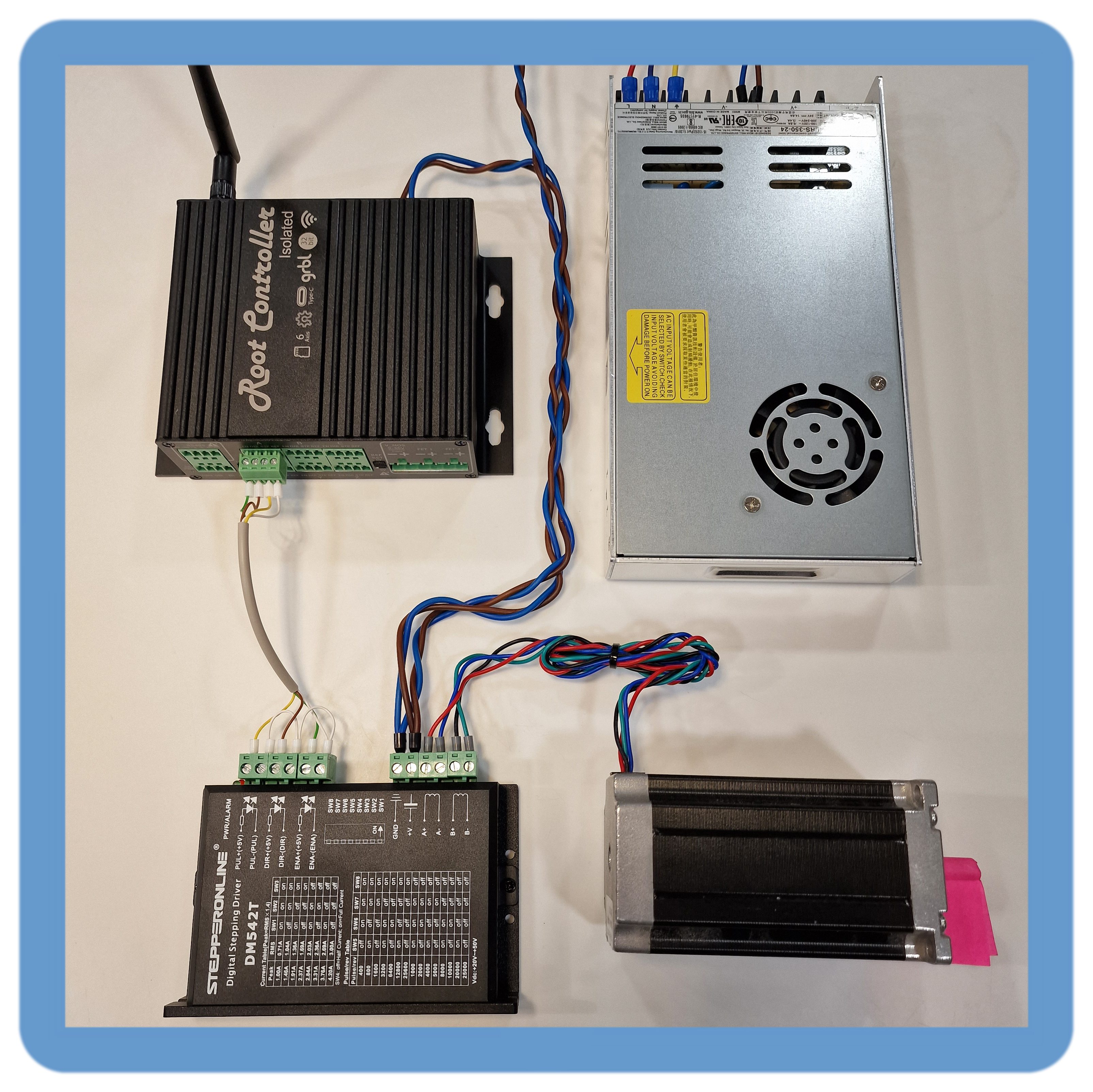
- DM542
- DM556
- DM860
¶ Fuildnc motor configuration (Common Cathode)
      x:
        steps_per_mm: 160.000
        max_rate_mm_per_min: 4500.000
        acceleration_mm_per_sec2: 500.000
        max_travel_mm: 100
        soft_limits: true
        homing:
          cycle: 1
          positive_direction: true
          mpos_mm: 100
          feed_mm_per_min: 100.000
          seek_mm_per_min: 800.000
          settle_ms: 500
          seek_scaler: 1.100
          feed_scaler: 1.100

        motor0:
          limit_neg_pin: NO_PIN
          limit_pos_pin: NO_PIN
          limit_all_pin: NO_PIN
          hard_limits: true
          pulloff_mm:1.000
          standard_stepper:
            step_pin: I2SO.7:low
            direction_pin: I2SO.5:low
            disable_pin: I2SO.3:high
Motor definition for the X motor port
  y:
    steps_per_mm: 160.000
    max_rate_mm_per_min: 4500.000
    acceleration_mm_per_sec2: 500.000
    max_travel_mm: 100.000
    soft_limits: true
    homing:
      cycle: 1
      positive_direction: true
      mpos_mm: 100
      feed_mm_per_min: 100.000
      seek_mm_per_min: 800.000
      settle_ms: 500
      seek_scaler: 1.100
      feed_scaler: 1.100

    motor0:
      limit_neg_pin: NO_PIN
      limit_pos_pin: NO_PIN
      limit_all_pin: NO_PIN
      hard_limits: true
      pulloff_mm:1.000
      standard_stepper:
        step_pin: I2SO.12:low
        direction_pin: I2SO.10:low
        disable_pin: I2SO.8:high
Motor definition for the Y motor port
  z:
    steps_per_mm: 160.000
    max_rate_mm_per_min: 4500.000
    acceleration_mm_per_sec2: 500.000
    max_travel_mm: 100.000
    soft_limits: true
    homing:
      cycle: 1
      positive_direction: true
      mpos_mm: 100
      feed_mm_per_min: 100.000
      seek_mm_per_min: 800.000
      settle_ms: 500
      seek_scaler: 1.100
      feed_scaler: 1.100

    motor0:
      limit_neg_pin: NO_PIN
      limit_pos_pin: NO_PIN
      limit_all_pin: NO_PIN
      hard_limits: true
      pulloff_mm:1.000
      standard_stepper:
        step_pin: I2SO.18:low
        direction_pin: I2SO.16:low
        disable_pin: I2SO.14:high
Motor definition for the Z motor port
  a:
    steps_per_mm: 160.000
    max_rate_mm_per_min: 4500.000
    acceleration_mm_per_sec2: 500.000
    max_travel_mm: 100.000
    soft_limits: true
    homing:
      cycle: 1
      positive_direction: true
      mpos_mm: 100
      feed_mm_per_min: 100.000
      seek_mm_per_min: 800.000
      settle_ms: 500
      seek_scaler: 1.100
      feed_scaler: 1.100

    motor0:
      limit_neg_pin: NO_PIN
      limit_pos_pin: NO_PIN
      limit_all_pin: NO_PIN
      hard_limits: true
      pulloff_mm:1.000
      standard_stepper:
        step_pin: I2SO.6:low
        direction_pin: I2SO.4:low
        disable_pin: I2SO.2:high
Motor definition for the A motor port
  b:
    steps_per_mm: 160.000
    max_rate_mm_per_min: 4500.000
    acceleration_mm_per_sec2: 500.000
    max_travel_mm: 100.000
    soft_limits: true
    homing:
      cycle: 1
      positive_direction: true
      mpos_mm: 100
      feed_mm_per_min: 100.000
      seek_mm_per_min: 800.000
      settle_ms: 500
      seek_scaler: 1.100
      feed_scaler: 1.100

    motor0:
      limit_neg_pin: NO_PIN
      limit_pos_pin: NO_PIN
      limit_all_pin: NO_PIN
      hard_limits: true
      pulloff_mm:1.000
      standard_stepper:
        step_pin: I2SO.13:low
        direction_pin: I2SO.11:low
        disable_pin: I2SO.9:high
Motor definition for the B motor port
  c:
    steps_per_mm: 160.000
    max_rate_mm_per_min: 4500.000
    acceleration_mm_per_sec2: 500.000
    max_travel_mm: 100.000
    soft_limits: true
    homing:
      cycle: 1
      positive_direction: true
      mpos_mm: 100
      feed_mm_per_min: 100.000
      seek_mm_per_min: 800.000
      settle_ms: 500
      seek_scaler: 1.100
      feed_scaler: 1.100

    motor0:
      limit_neg_pin: NO_PIN
      limit_pos_pin: NO_PIN
      limit_all_pin: NO_PIN
      hard_limits: true
      pulloff_mm:1.000
      standard_stepper:
        step_pin: I2SO.19:low
        direction_pin: I2SO.17:low
        disable_pin: I2SO.15:high
Motor definition for the Y motor port
Ganging two motors together can be implemented with the following motor definition:
(In this example I use the X Motor and A motor port)
  x:
    steps_per_mm: 160.000
    max_rate_mm_per_min: 4500.000
    acceleration_mm_per_sec2: 500.000
    max_travel_mm: 100
    soft_limits: true
    homing:
      cycle: 1
      positive_direction: true
      mpos_mm: 100
      feed_mm_per_min: 100.000
      seek_mm_per_min: 800.000
      settle_ms: 500
      seek_scaler: 1.100
      feed_scaler: 1.100

    motor0:
      limit_neg_pin: NO_PIN
      limit_pos_pin: NO_PIN
      limit_all_pin: NO_PIN
      hard_limits: true
      pulloff_mm:1.000
      standard_stepper:
        step_pin: I2SO.7:low
        direction_pin: I2SO.5:low
        disable_pin: I2SO.3:high
    motor1:
      limit_neg_pin: NO_PIN
      limit_pos_pin: NO_PIN
      limit_all_pin: NO_PIN
      hard_limits: true
      pulloff_mm:1.000
      standard_stepper:
        step_pin: I2SO.6:low
        direction_pin: I2SO.4:low
        disable_pin: I2SO.2:high
Any axis can have ganged motors! upto a total of 6 motors per controller. This is an example axis configuration.
Ganging two motors together can be implemented with the following motor definition. This configuration is used on the Root CNC series.
(In this example I use the Y Motor and B motor port)
  y:
    steps_per_mm: 160.000
    max_rate_mm_per_min: 4500.000
    acceleration_mm_per_sec2: 500.000
    max_travel_mm: 100.000
    soft_limits: true
    homing:
      cycle: 1
      positive_direction: true
      mpos_mm: 100
      feed_mm_per_min: 100.000
      seek_mm_per_min: 800.000
      settle_ms: 500
      seek_scaler: 1.100
      feed_scaler: 1.100

    motor0:
      limit_neg_pin: NO_PIN
      limit_pos_pin: NO_PIN
      limit_all_pin: NO_PIN
      hard_limits: true
      pulloff_mm:1.000
      standard_stepper:
        step_pin: I2SO.12:low
        direction_pin: I2SO.10:low
        disable_pin: I2SO.8:high
    motor1:
      limit_neg_pin: NO_PIN
      limit_pos_pin: NO_PIN
      limit_all_pin: NO_PIN
      hard_limits: true
      pulloff_mm:1.000
      standard_stepper:
        step_pin: I2SO.13:low
        direction_pin: I2SO.11:low
        disable_pin: I2SO.9:high
Any axis can have ganged motors! upto a total of 6 motors per controller. This is an example axis configuration.
¶ grblHAL motor configuration (Common Cathode)
Comming soon
Comming soon
Comming soon
Comming soon
Comming soon
Comming soon
¶ Inputs
The Root controller ISO has isolated inputs which are referenced to the Vin section of the card. Please take note of the isolation boundaries when connecting up the inputs.
The Controller is designed to support normal volt-free switch; such as mechanical switches, either NC (normally closed) or NO (normally open); And/Or NPN inductive sensors. All inputs are electrically the same. For ease of wiring, all axis limit inputs have the same connector and pin out.
The inputs which are used for “start”, “hold” and “macro” do have a different connector, so please take note of the difference in wiring. Again easy to wiring, Root CNC offer a easy button/ probe point PCB. These can be purchased from the store or downloaded from GitHub.
All inputs are software configured and can be repurposed.
| Rev 3 | Rev 2.1 | Rev 2.0 | |
|---|---|---|---|
| Axis Inputs | 6 | 6 | 6 |
| Probe Input | 1 | 1 | 1 |
| User Configurable | 1 | 3 | 3 |
Please note all input listed in the table are software configurable inputs which can be used for any function.
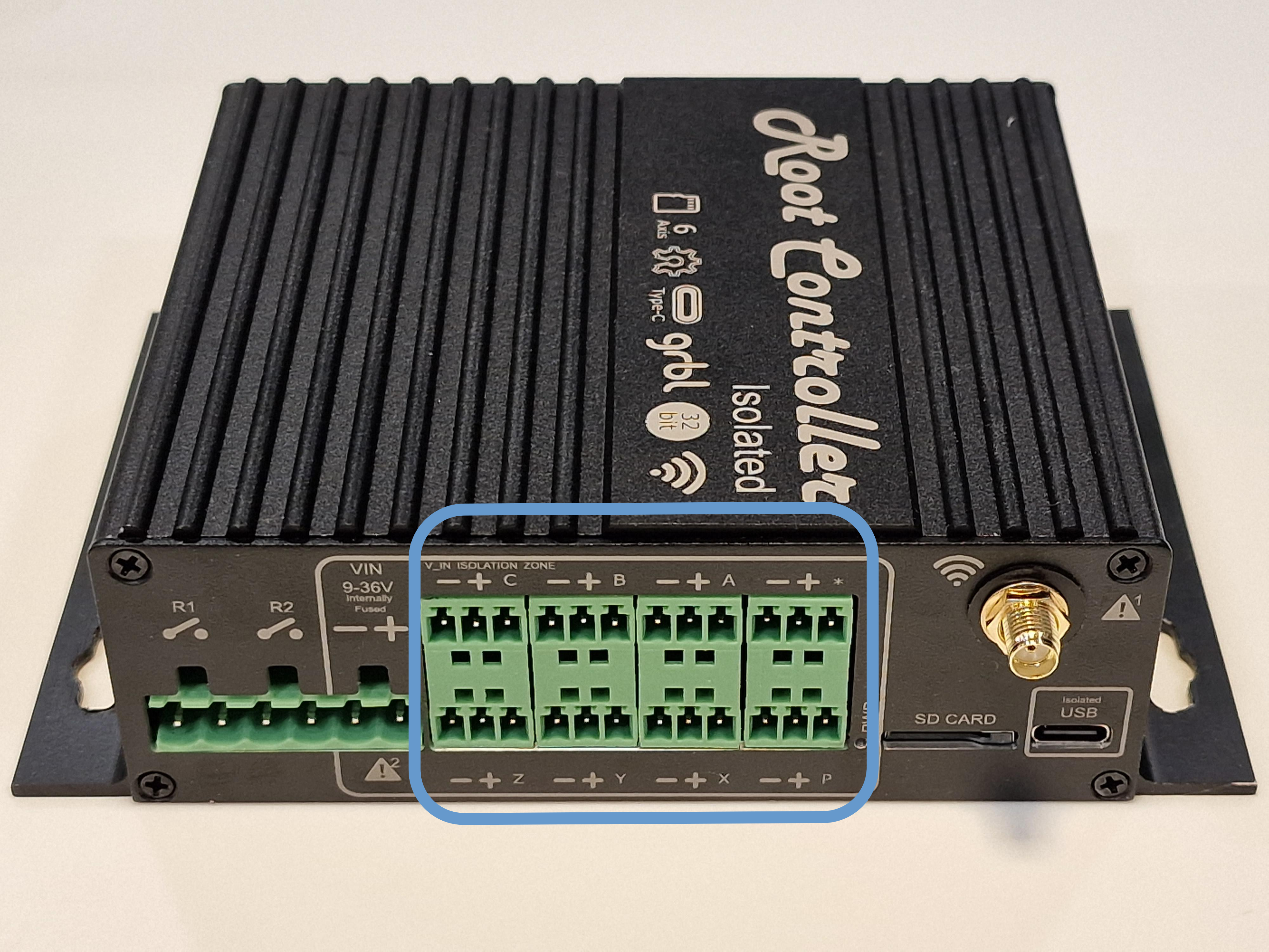
- axis inputs (one per axis, min and max can be combined onto on input. Please see the end stop section for more information)
- x1 probe point (used to auto tool height correction of edge finding)
- user configurable inputs (these are typically used for GRBL control signals such as Start, Hold, Reset and Macros.
¶ Endstops
As mentioned in the pervious section, the Root controller is designed to accommodate voltage free switches, such as mechanical lever switches or NPN inductive switches.
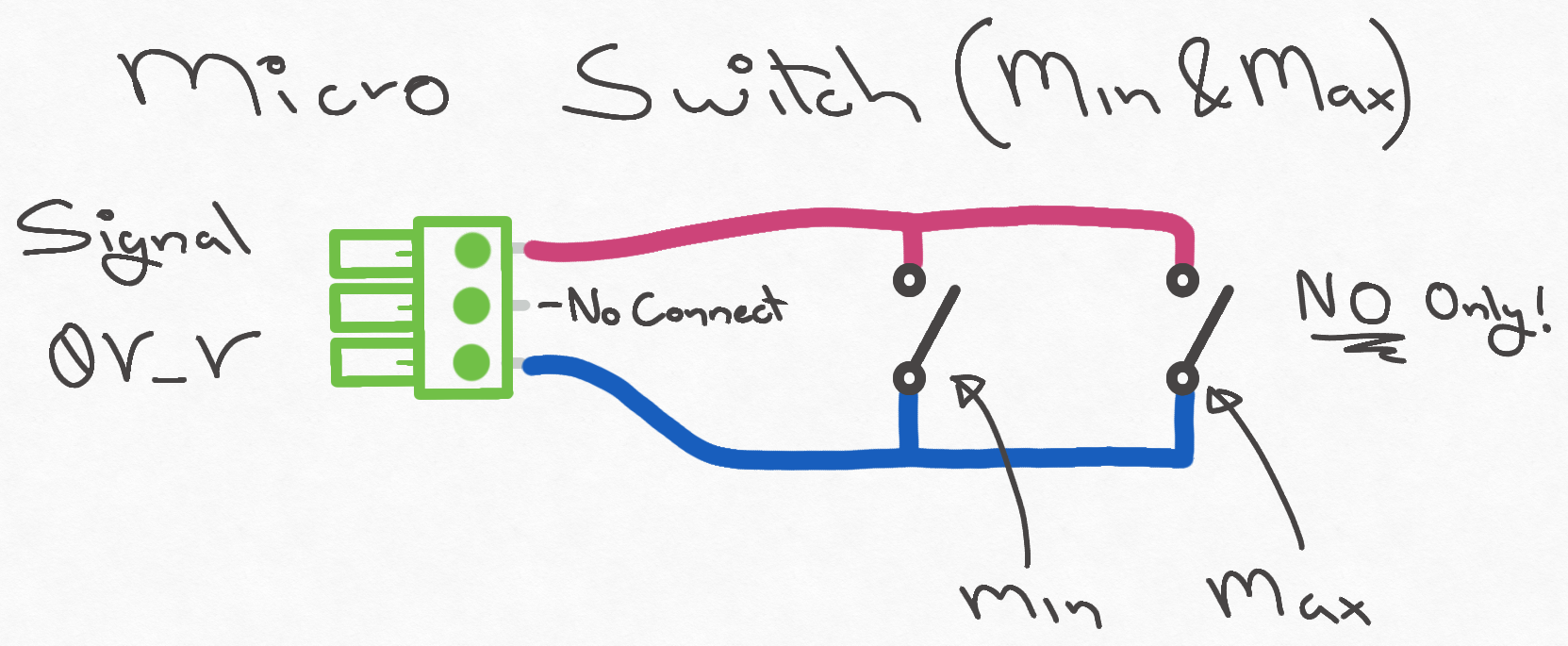
Each input can have two sensors/ switches connected to it, these are typically used on axis with min and max limit switches.
¶ Inductive Probe Wiring
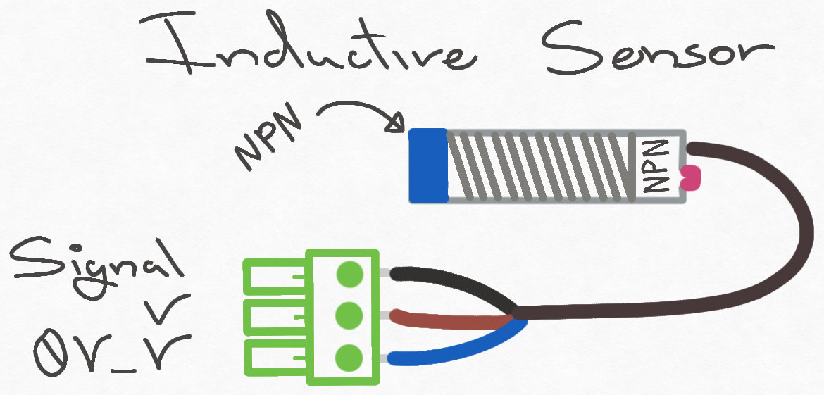
NPN Inductive Switch sensor ONLY
¶ Inductive Probe Min & Max Wiring
Image comming soon
¶ Basic Endstop Wiring
In this basic configuration, either NO (Normally Open) Or NC (Normally Closed) switches can be used
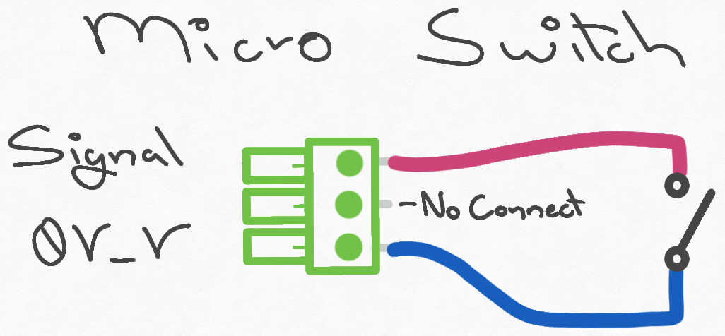
¶ Endstop wiring Min & Max (NO)
¶ Endstop wiring Min & Max (NC)

Please note REV 2.1/REV 2.0 - NC switches are not recommend on
Y_lim. IF YOU INTEND TO FLASH THE ROOT CONTROLLER WHILST BEING INSTALLED IN A SYSTEMS. pulling these pins LOW stops the programming routing. If you do use NC switched: then, please ensure these are disconnected piror to programming.
¶ Outputs
Aside from the digital outputs of the stepper driver port (Please see # Stepper control for more information). The Root Controller has the additional outputs:
| Rev 3 | Rev 2.1 | Rev 2.0 | |
|---|---|---|---|
| MOSFET output (Isolated control) | 2 | 3 | 3 |
| High power relays | 2 | 3 | 3 |
| Laser/ spindle port (none isolated) | PWM, DIR, EN | PWM, DIR, EN | PWM, DIR, EN |
- MOSFET output, great for turning lights or solenoids on/off
- High power relays output, perfectly suited for turning shop vacs on or dust extractors
- Laser/ spindle port, perfect for controlling a PWM device
¶ MOSFETS
The Root controller has a number of high power MOSFETs which can be used to switch the power to a number of device, such as solenoids, lights and DC motors.
The power supply is fed by its dedicated power connector. The input power is internally fused for added protection. The supply can be separate or tied to other supplies depending on your configuration.
The MOSFET area is perfectly suited for switching inductive loads such a solenoids or relays.
| Rev 3 | Rev 2.1 | Rev 2.0 | |
|---|---|---|---|
| PWM | 1 (FET_1) | 2 (FET_1/2) | 2 (FET_1/2) |
| ON/ OFF controller | 1 | 1 | 1 |
| Total | 2 | 3 | 3 |
MOSFET control = on/off control and PWM control (Hardware dependant)
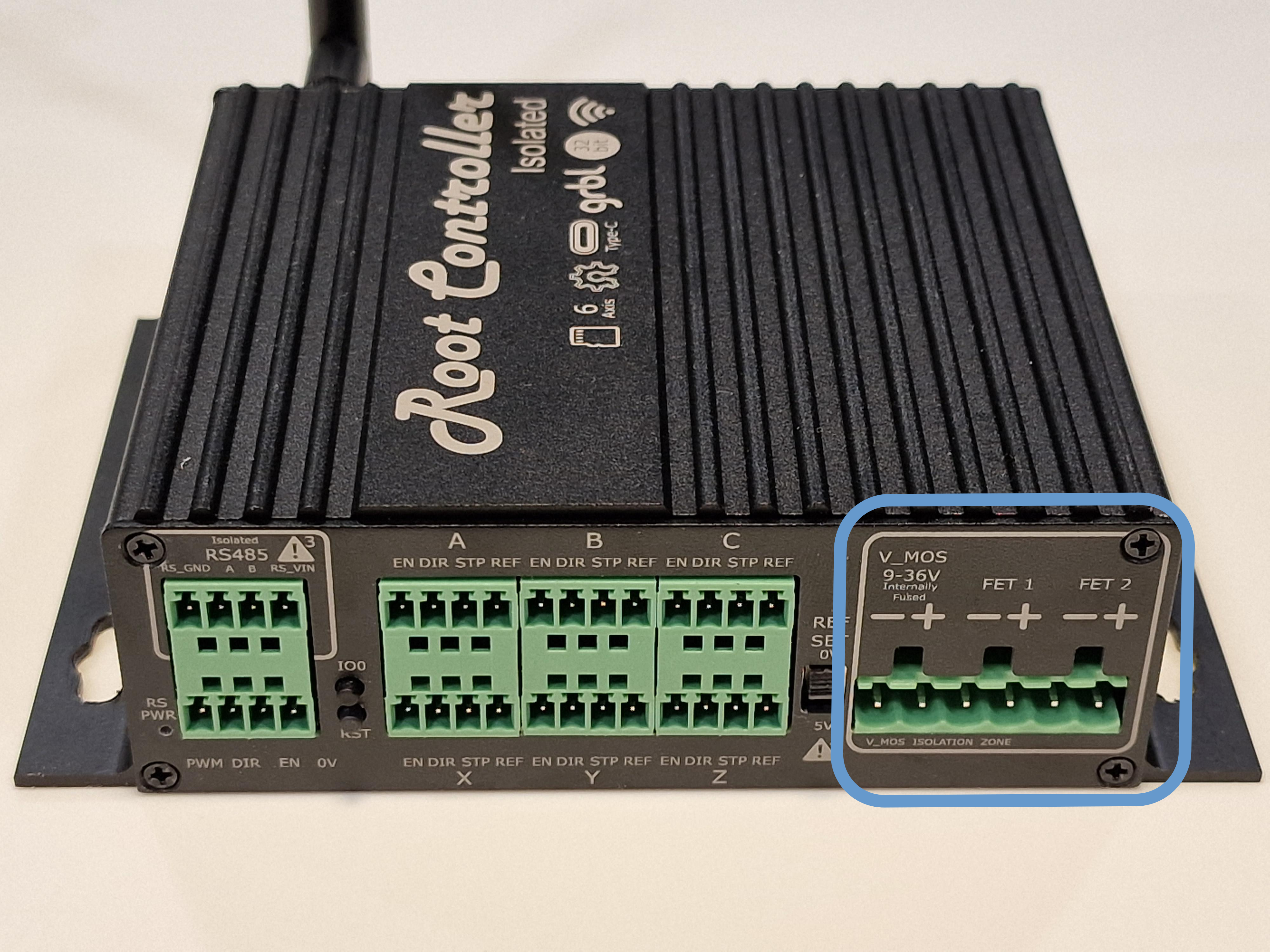
Please note depending on the software configuration, not all MOSFET or RELAY output can be used at the same time.
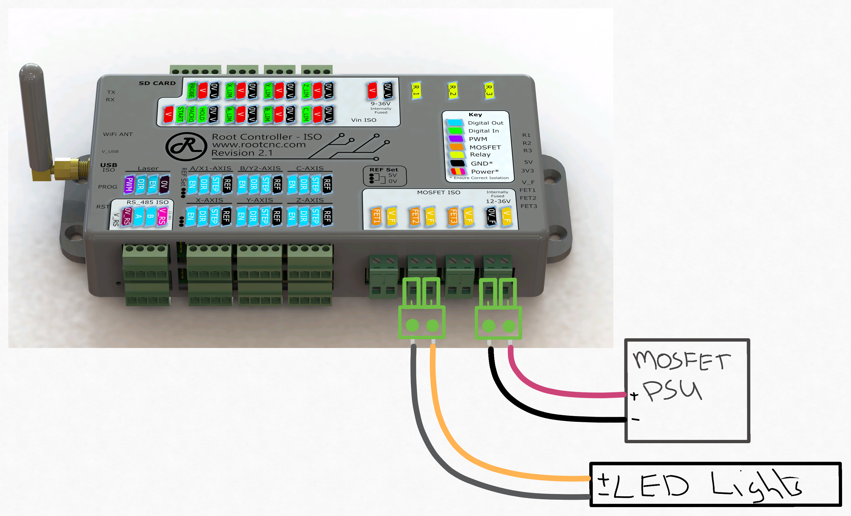
MOSFET control
- FET_1 - on/off control
- FET_2 - on/off control
- FET_3 - on/off control
Please note depending on the software configuration, not all MOSFET or RELAY output can be used at the same time.
¶ Relay output
The Root controller has a number relays outputs which can be used to switch high power loads, such as dust extractors, fume extractors and vacum cleaners.
These relays are capable of switching mains power with a current of 13A.
| Rev 3 | Rev 2.1 | Rev 2.0 | |
|---|---|---|---|
| On/ Off control Relau | 2 | 3 | 3 |
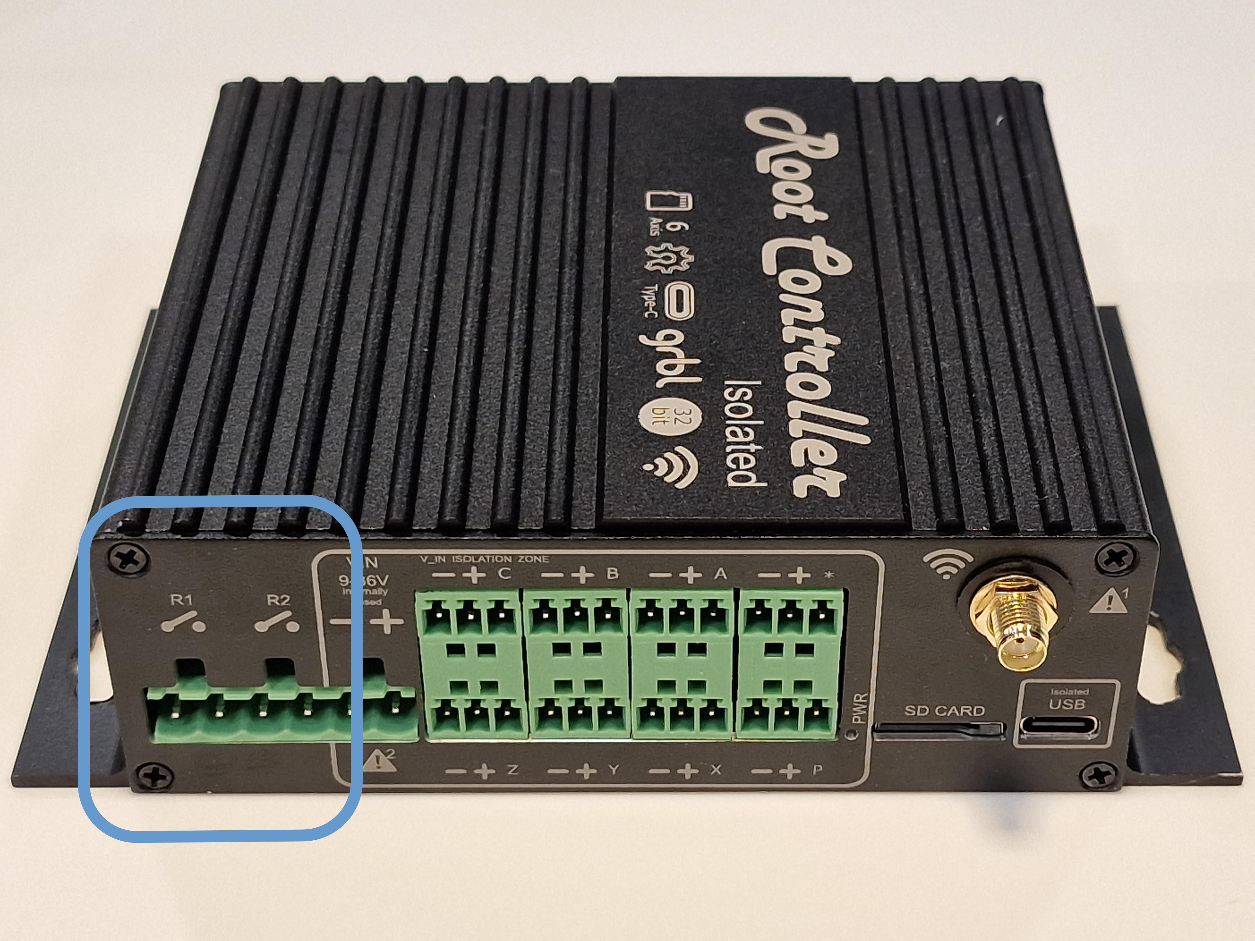
Please note depending on the software configuration, not all MOSFET or RELAY output can be used at the same time.
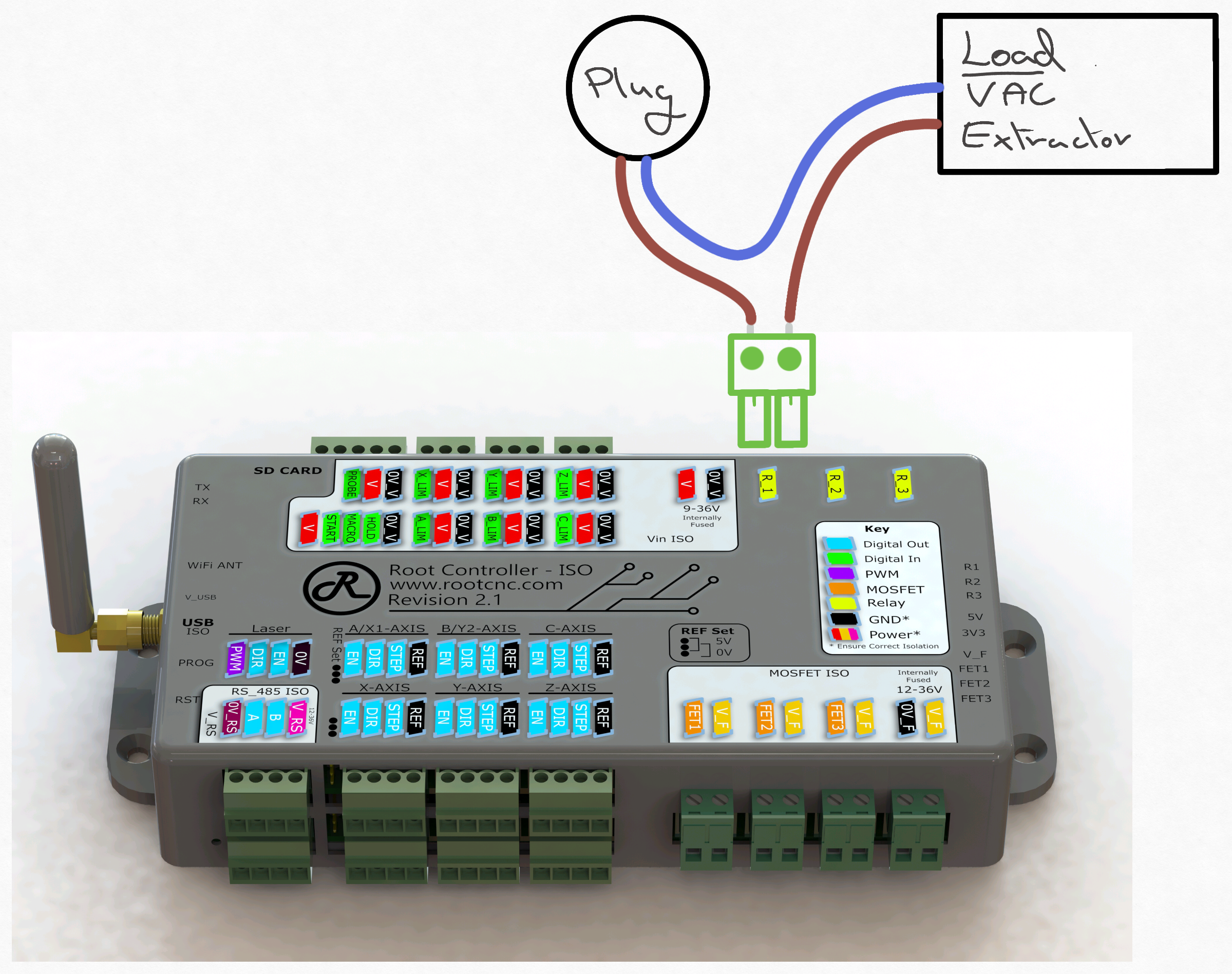
Please note depending on the software configuration, not all MOSFET or RELAY output can be used at the same time.
¶ PWM laser/ Spindle output
The Root controller has a discrete output port which can be used to control a number of different devices. For example: lasers, and discrete control spindles.
Laser/ Spindle control
- EN - on/off control
- DIR - on/off control
- PWM - on/off control & PWM Control
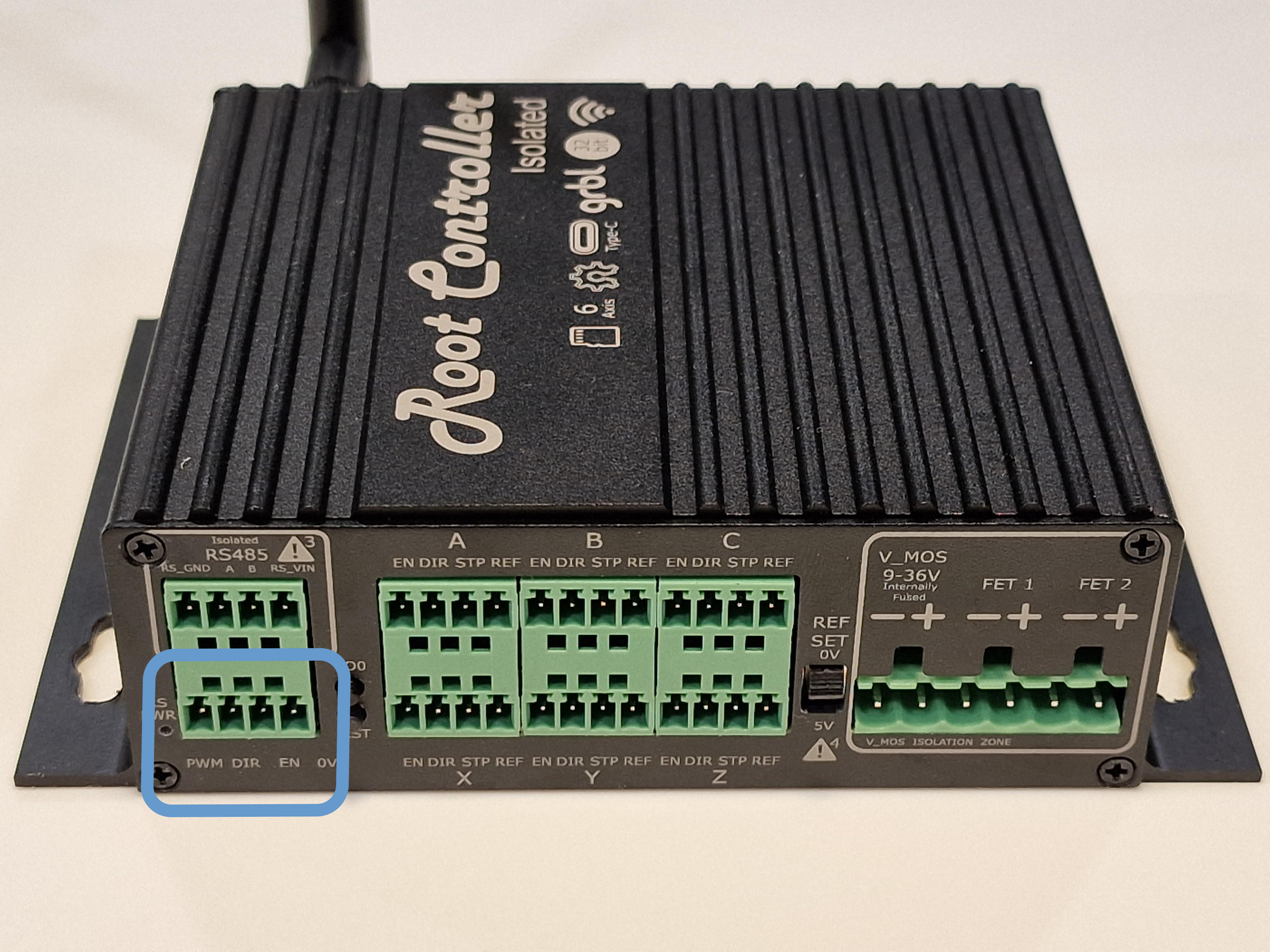
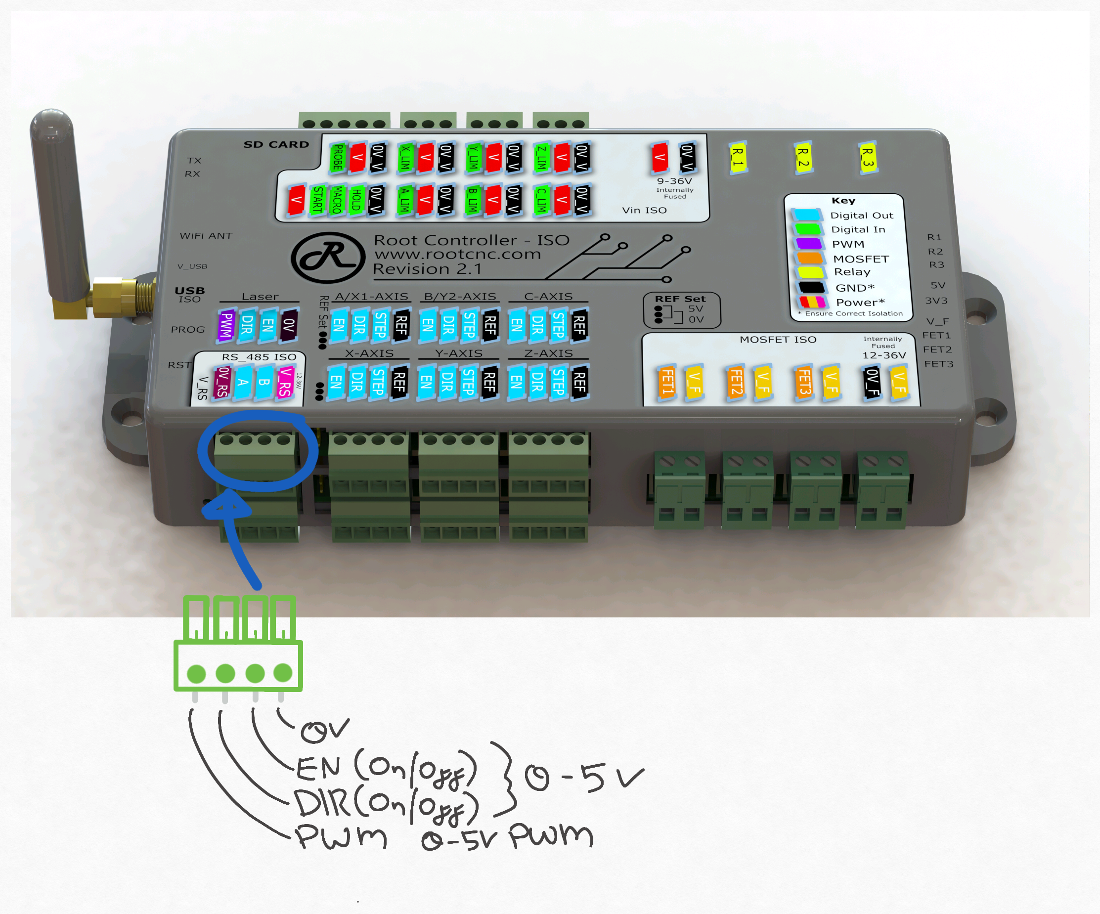
For spindle control, it is advised you use a MODBUS/ RS485 VFD and communicated through the isolated spindle interface.
This port is NOT isolated so careful consideration is needed when connecting external devices to ensure the isolation zones are not violated
¶ Isolated RS485
The Root controller offers a fully isolated RS485/ MODBUS interface. This interface allows communication between the controller and a VFD spindle motor (OR other device - Software dependant).
This interface is intended to be to a small isolated area which is powered form the VFD or downstream connected device. for full operating range, please see the electrical specification below.
All versions of the Root Controller ISO offer the isolated RS485 interface
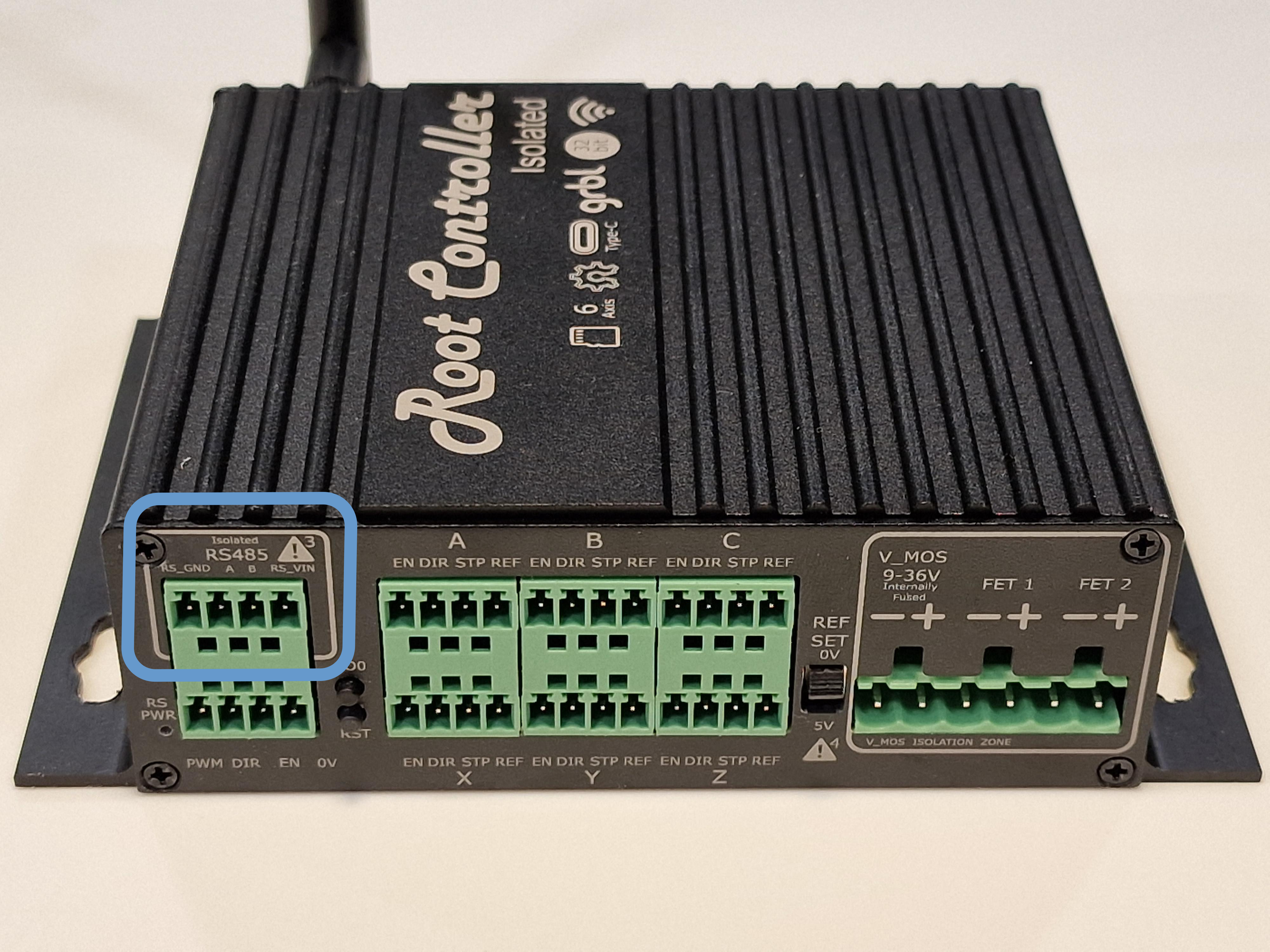
Please note this interface will not work unless externally powered
¶ SD CARD
The Root controller has expandable storage option in the form of an SD card. files can be sent over WIFI and stored on the SD for later use. this is particularly handy when running repetitive jobs. files can be accessed from a web browser over your local network.
For better compatibility, please use the older SD card rather than the newer ones.
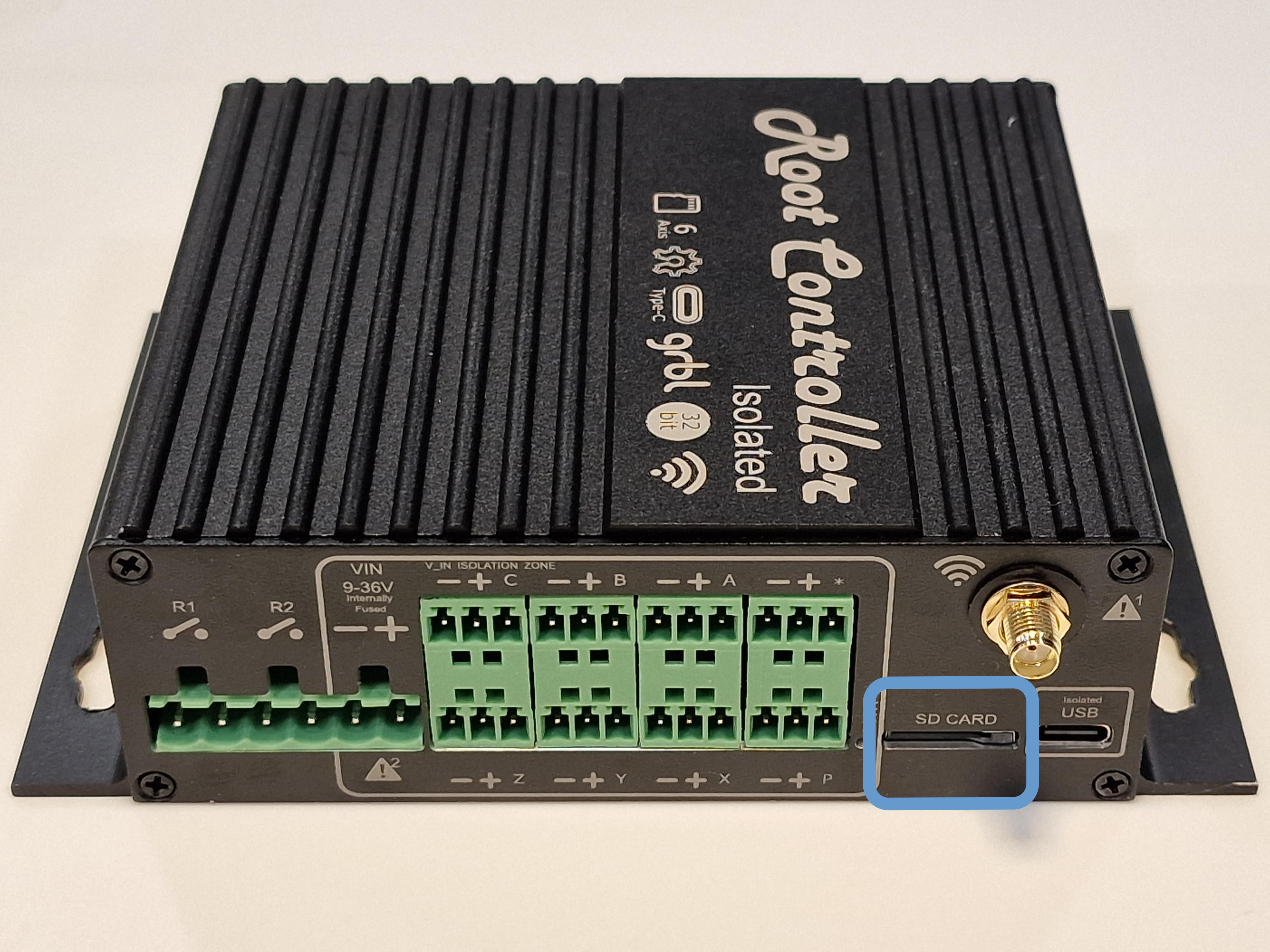
All versions of the Root Controller ISO offer a SD card interface
To enable the code please use the following in the configuration
spi:
  miso_pin: gpio.19
  mosi_pin: gpio.23
  sck_pin: gpio.18

sdcard:
  card_detect_pin: NO_PIN
  cs_pin: gpio.5
¶ WIFI / Blutooth
The Root controller offers wireless capability. this allows controller of the machine through your local network or via a mobile phone and blutooth.
As EMC and isolation is a concern; careful positioning and placement of the antenna is critical for optimum performance. The Root Controller had implemented an internal antenna with the goal to reduce the cost of the controller. but this led to poor WIFI coverage; for this reason, the new versions of the Root controller offer an external antenna with can be extended using a standard SMA extension lead.
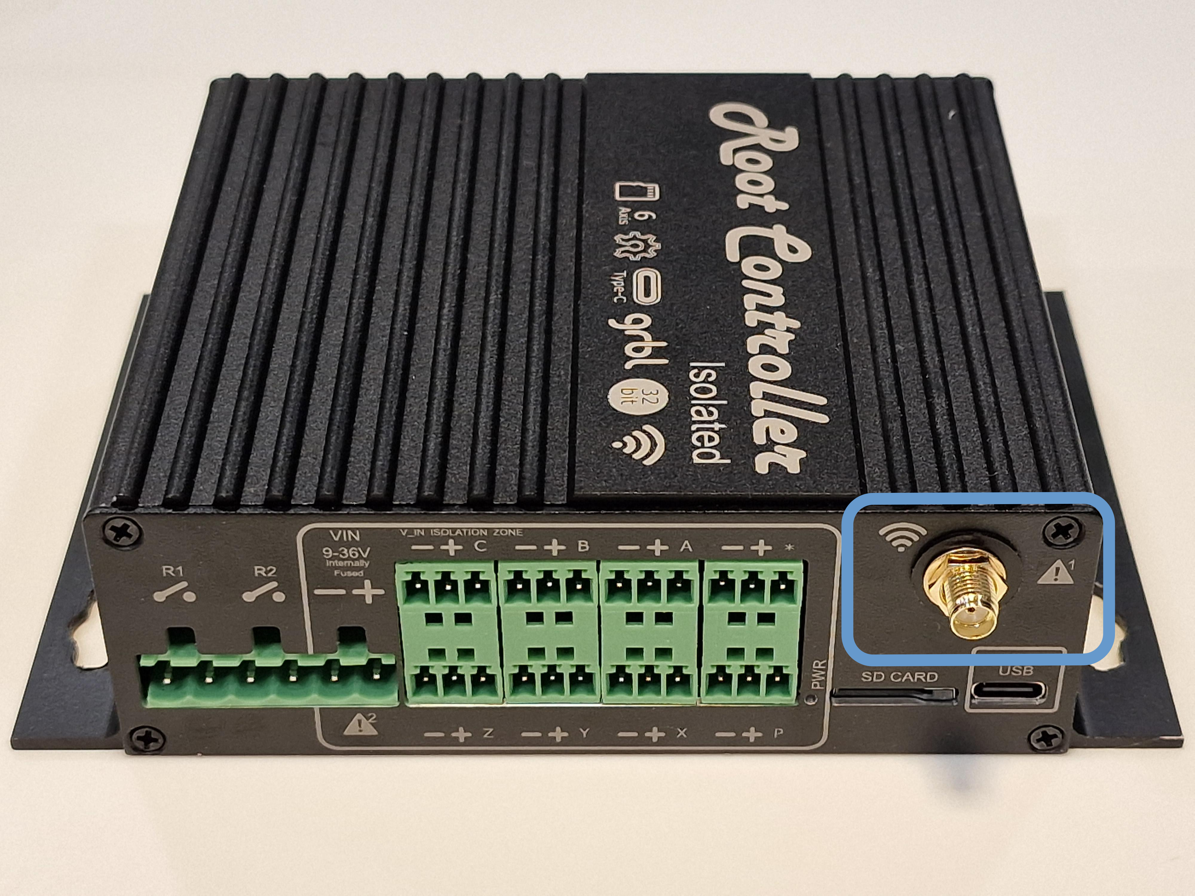
Please note: the outer shield of the Antenna is connected to an internal reference plane. you MUST NOT connect this to Chassis or any other return planes as this will ruin your isolated setup. you will note the antenna port on the newer Rev 3 and onwards controllers has isolation washer between the case and the connector. This is to stop this connection from happening. If you intend to extend this internal for better antenna performance, or outside and electrical cabinet - please ensure the isolation boundaries of isolation are kept.
| Rev 3 | Rev 2.1 | Rev 2.0 | Beta Card | |
|---|---|---|---|---|
| WIFI Antenna | External | External | Internal | Internal |
¶ Pin mapping
The Root controller comes in different forms, please select the tab that matches your hardware revision
¶ I2S Output Port Mapping
I2S Bus is purely outputs ONLY.
| Port | Description | Port | Description | Port | Description |
|---|---|---|---|---|---|
| I2S_0 | LASER_DIR | I2S_8 | Y_EN | I2S_16 | Z_DIR |
| I2S_1 | LASER_EN | I2S_9 | B_EN | I2S_17 | C_DIR |
| I2S_2 | A_EN | I2S_10 | Y_DIR | I2S_18 | Z_STEP |
| I2S_3 | X_EN | I2S_11 | B_DIR | I2S_19 | C_STEP |
| I2S_4 | A_DIR | I2S_12 | Y_STEP | I2S_20 | RELAY_2 |
| I2S_5 | X_DIR | I2S_13 | B_STEP | I2S_21 | RELAY_1 |
| I2S_6 | A_STEP | I2S_14 | Z_EN | I2S_22 | FET_2 |
| I2S_7 | X_STEP | I2S_15 | C_EN | I2S_23 | NOT USED |
¶ ESP32 Mapping
| Port | Description | Port | Description | Port | Description |
|---|---|---|---|---|---|
| GPIO2 | P-PIN | GPIO17 | RS_485_TX | GPIO27 | Z-PIN |
| GPIO4 | RS_485_DE_RE | GPIO18 | SD_CLK | GPIO32 | Y-PIN |
| GPIO5 | SD_CS | GPIO19 | SD_MISO | GPIO33 | LASER PWM |
| GPIO12 | SHIFT_DATA | GPIO21 | SHIFT_STR_CLK | GPIO34 | X-PIN |
| GPIO13 | FET_1 (PWM) | GPIO22 | SHIFT_CLK | GPIO35 | B-PIN |
| GPIO14 | C-PIN | GPIO23 | SD_MOSI | GPIO36 | INTERNAL TEST POINT |
| GPIO15 | *-PIN | GPIO25 | INTERNAL TEST POINT | GPIO39 | INTERNAL TEST POINT |
| GPIO16 | RS_485_RX | GPIO26 | A-PIN |
This list support the revision 2.0 Onwards. If you're after an earlier version pin out please see the version history on Github
¶ I2S Output Port Mapping
I2S Bus is purely outputs ONLY.
| Port | Description | Port | Description | Port | Description | Port | Description |
|---|---|---|---|---|---|---|---|
| I2S_0 | X_EN_PIN | I2S_8 | Z_EN_PIN | I2S_16 | SPINDLE_DIR | I2S_24 | B_EN_PIN |
| I2S_1 | X_DIRECTION_PIN | I2S_9 | Z_DIRECTION_PIN | I2S_17 | SPINDLE_EN | I2S_25 | B_DIRECTION_PIN |
| I2S_2 | X_STEP_PIN | I2S_10 | Z_STEP_PIN | I2S_18 | SPARE_1 | I2S_26 | B_STEP_PIN |
| I2S_3 | X_CS - NOT USED | I2S_11 | Z_CS - NOT USED | I2S_19 | SPARE_2 | I2S_27 | B_CS - NOT USED |
| I2S_4 | Y_EN_PIN | I2S_12 | FET_1 | I2S_20 | A_EN_PIN | I2S_28 | C_EN_PIN |
| I2S_5 | Y_DIRECTION_PIN | I2S_13 | RELAY_1 | I2S_21 | A_DIRECTION_PIN | I2S_29 | C_DIRECTION_PIN |
| I2S_6 | Y_STEP_PIN | I2S_14 | RELAY_2 | I2S_22 | A_STEP_PIN | I2S_30 | C_STEP_PIN |
| I2S_7 | Y_CS - NOT USED | I2S_15 | RELAY_3 | I2S_23 | A_CS - NOT USED | I2S_31 | C_CS - NOT USED |
¶ ESP32 Mapping
| Port | Description | Port | Description | Port | Description |
|---|---|---|---|---|---|
| GPIO2 | Y-PIN | GPIO17 | RS_485_TX | GPIO27 | PROBE-PIN |
| GPIO4 | RS_485_DE_RE | GPIO18 | SD_CLK | GPIO32 | B-PIN |
| GPIO5 | SD_CS | GPIO19 | SD_MISO | GPIO33 | FET_2 |
| GPIO12 | SHIFT_DATA | GPIO21 | SHIFT_STR_CLK | GPIO34 | GRBL_MACRO |
| GPIO13 | FET_3 | GPIO22 | SHIFT_CLK | GPIO35 | A-PIN |
| GPIO14 | C-PIN | GPIO23 | SD_MOSI | GPIO36 | GRBL_HOLD |
| GPIO15 | Z-PIN | GPIO25 | DAC_OUT/PWM | GPIO39 | GRBL_START |
| GPIO16 | RS_485_RX | GPIO26 | X-PIN |
¶ Electrical Specification
If you require additional information I have missed, please contact me and I'll get it added.
¶ Primary PSU
This is denoted a V and 0V_V for supply and return respectively on the case sticker.
Power is applied through its own dedicated fused port.
| Parameter | Min | Typ | Max | Unit |
|---|---|---|---|---|
Vin (V wrt 0V_V) |
9 | 24 | 36 | V |
| Current (Fuse Protected) [1] | 0.86 | 5[2] | A | |
Input Isolation voltage [V vs 0V[3]] |
1.5 | KV |
¶ Input
The inputs to the Root controller are referenced to the 0V_V of the Primary PSU. All input are isolated to the rest of the system.
To ensure optimal performance and noise immunity - please ensure the current return paths and loops are reduced and power zone references are not connected together. E.g. avoid connecting
0Vto0V_V
The Input are arranged to accept either an Open-Collector/ Open-Drain switch or a standard mechanical switch. Depending on the Primary PSU voltage this switching current will vary.
| Parameter | Condition | Min | Typ | Max | Unit |
|---|---|---|---|---|---|
| Switching Current | (*1) | 2.7 | 10 | mA | |
| V = 12V | 2.7 | mA | |||
| V = 24V | 5.8 | mA | |||
| V = 36V | 8.9 | mA |
- (1) Over full operating conditions
¶ RS485
This section is denoted by V_RS and 0V_RS respectively for the Power in and 0V for the isolated RS485 port.
| Parameter | Min | Typ | Max | Unit |
|---|---|---|---|---|
Vin (V_RSwrt 0V_RS) |
8.1 | 12 | 36 | V |
| Current Draw | 1.6 | 2 | mA | |
Basic DC Isolation [V_RS vs 0V] |
1.517 | KV | ||
Reinforced DC Insulation [V_RS vs 0V] [4] |
0.757 | KV | ||
Basic bipolar AC Isolation [V_RS vs 0V] [4:1] |
565 | V | ||
Reinforced bipolar AC Insulation [V_RS vs 0V] [5] |
565 | V | ||
| Differential Input Threshold Voltage, Vth | -200 | -125 | -30 | mV |
| Input Hysteresis | 20 | mV | ||
| Input Resistance (A, B) (*2) | 96 | 150 | kΩ | |
| Output High Voltage | 4.6 | 4.9 | V | |
| Output Low Voltage | 0.1 | 0.4 | V | |
| Output Short-Circuit Current | 7 | 85 | mA | |
ESD Rating (A,B) |
HMB (+/-2KV) |
¶ Digital Output (Stepper Outputs)
Isolation is achieved by using Opto-Isolated Stepper motor drivers such as "DM556"
| Parameter | Min | Typ | Max | Unit |
|---|---|---|---|---|
| Vout (Root controller derived supply) | 4.95 | 5 | 5.05 | V |
| Output current | 150 | mA | ||
| IOH High-level output current [6] | 25 | mA | ||
| IOL Low-level output current [6:1] | 25 | mA | ||
| VOH High-level output voltage [7] | 3.8 | V | ||
| VOL Low-level output voltage [8] | 0.55 | V |
¶ MOSFET Isolation
The Root Controller provides two (Rev 3) or Three (Rev 2.0/2.0) MOSFET controller switches. These switches have their own dedicated input power supply and can be driven from a separate PSU or the same PSU as V to allow for greater flexibility. The output are isolated internally to allow switching over noisey equipment, such as solinoides or other inductive switching elements.
| Parameter | Min | Typ | Max | Unit |
|---|---|---|---|---|
Vin (V_F wrt 0V_F) |
12 | 15 | 36 | V |
| Current (Fuse Protected) [9] | 0.001 | [10] | A |
¶ Relay
The Root controller has three NO relays (the Normally closed Pole is not accessible). These are design to allow the user to switch large main powered loads, such as Dust extraction, compressors and even lighting.
| Parameter | Min | Typ | Max | Unit |
|---|---|---|---|---|
| Switch Voltage DC | 300 | V | ||
| Switch Voltage AC | 440 | V | ||
| Contact Resistance | 100 | mOhm | ||
| Switch Current (Resistive Load) | 12 | A | ||
| Max Switch Power | 3000 | VA | ||
| Endurance (Switch Cycles) | 1x10^7 |
¶ USB
The USB port on the Root controller is a Type-C 2.0 UFP.
This port is also isolated with the
0V
| Parameter | Min | Typ | Max | Unit |
|---|---|---|---|---|
Voltage (V_USB to 0V_USB) |
4.5 | 5 | 5.5 | V |
| Current | 5 | 8 | 10 | mA |
| Data Rate | 12 | Mbps | ||
| DC Basic Isolation | 849 | V | ||
| AC Bipolar Basic Isolation | 849 | V | ||
| AC Unipolar Basic Isolation | 560 | V |
¶ Software Configurations
For basic configurations for your machine, please see the sub folder names "Configurations"
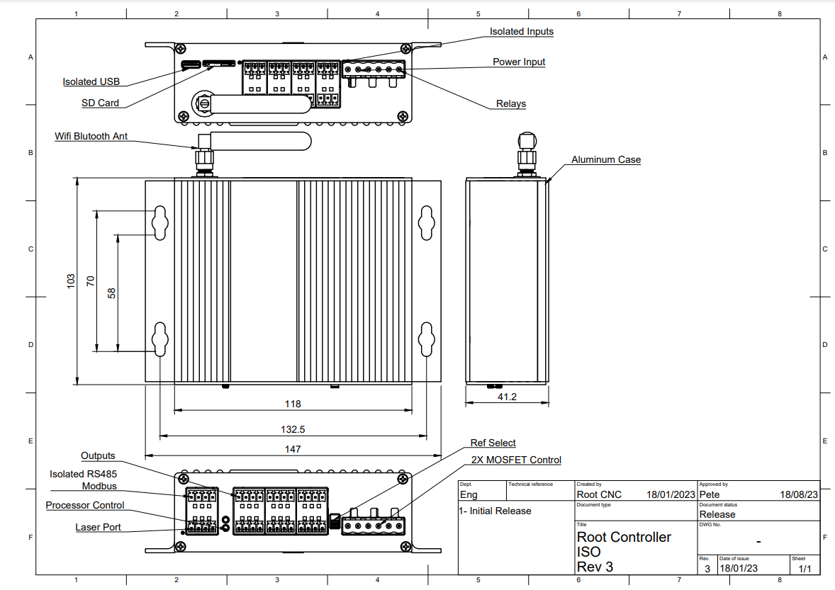
¶ Mechanical dimensions
¶ 3D CAD Models
Comming soon
Comming soon
¶ Social links
- Facebook Group
- Discourse
- Discord Great for quick answer to questions and firmware support
- Thingiverse
- Youtube
¶ License
This project is licensed under the Creative Commons 4.0 license with
Attribution-NonCommerial-ShareAlike see LICENSE.txt for details
This is current draw of the Root CNC controller including worst case power export via output pins. This does not induce the exported power on V pins (Such as powering inductive probes) ↩︎
Installed Micro fuse is 5A ↩︎
0V is the isolated floating voltage on the Root CNC controller – Do Not connect this to chassis ↩︎
RS485 does not contain a bus termination resistor - place provisioned. The Isolating RS485 has internal thresholds to detect logic levels. ↩︎
This parameter makes the Root CNC controller extremely well suited to drive opto-isolated stepper motor drivers (special sauce) ↩︎ ↩︎
Over full operating specification and at max current draw (-32mA) ↩︎
Over full operating specification and at max current draw (32mA) ↩︎
Current is dependant of the peripherals you connect to the controller ↩︎
Controller has an internal fuse - Rating is 35A ↩︎

